1
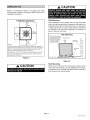
COMPRESSOR
RUN
CAPACITOR
SYSTEM OPERATION
MONITOR
CONTACTOR
/
VAPOR LINE
" GROUND
LUG
INLET AIR
,_
VAPOR VALVE
INLET
AIR
- AND GAUGE PORT
COMPRESSOR
POWER
TERMINALS
LIQUID LINE
" SERVICE VALVE
AND GAUGE
PORT
"_ FILTER DRIER
DISCHARGE
LINE
LOW PRESSURE
SWITCH
HIGH PRESSURE
SWITCH
"_
INLETAIR
TOP VIEW
PARTS ARRANGEMENT
ELECTRICAL
t
INLETS
_'_,,
VAPOR LINE INLET'_.
\\
LIQUID LINE INLET\xX\_
C
X
_
tDISCHARGE
AIR
.........................................................................
.......................................................................................................
4-1/2
A
(114)
2-9/16
(65)
D
-
(,)
II
I
_-_142)_1_
2
F -_C142_
1-3/8..._
!_
(35) "Yll
(51)
rE.
I_,..J 6-1/16L,=
"'-I (154)I_'
SIDE VIEW
Figure
1
HSXB15 Model
Dim.
-024
-030,-036,-042
-048
-060
A
27-7/8 (708)
30-7/8 (784)
34-7/8 (886)
40-7/8 (1038)
B
25-7/8 (657)
32-1/8 (816)
32-1/8 (816)
32-1/8 (816)
C
29-7/8 (759)
34-1/16 (865)
34-1/16 (865)
34-1/16 (865)
D
12-1/4 (311 )
12-3/4 (324)
13-3/4 (349)
19-3/4 (502)
E
22-7/16 (570)
26-5/8 (676)
26-5/8 (676)
26-5/8 (676)
These instructions are intended as a general guide and do
not supersede local codes in any way. Consult authorities
who have jurisdiction before installation.
Table 1
Torque
Requirements
Part
Recommended
Service valve cap
Sheet metal screws
8 ft.- lb.
16 in.- lb.
Torque
11 NM
2 NM
F
14-7/16 (367)
18-5/8 (473)
18-5/8 (473)
18-5/8 (473)
G
22-1/8 (562)
28-1/8 (718)
28-1/8 (718)
28-1/8 (718)
Machine screws #10
28 in.- lb.
3 NM
H
2-7/8 (73)
3-7/8 (98)
3-7/8 (98)
3-7/8 (98)
Compressor bolts
90 in.- lb.
10 NM
J
5-1/2 (140)
7-1/2 (191)
7-1/2 (191)
7-1/2 (191)
Gauge port seal cap
8 ft.- lb.
11 NM
Page 2
504710M
03/06