1
WARNING!
YOU WILL BE WORKING AROUND THE ENGINE AND EXHAUST SYSTEM
DURING INSTALLATION. ENSURE THAT THE ENGINE AND EXHAUST SYSTEM
HAVE FULLY COOLED TO PREVENT INJURY.
STEP 2
Remove the fasteners which secure the timing cover, the fasteners and cover
will no longer be used.
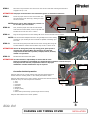
BEVELED PLATE AND BEAUTY
RING FOR EVO AND SPORTSTERS
PIC 1
Note: The flat plate with five holes is for twin cam motors. The beveled plate and
the spacer ring are for Evo and XL motors. PIC. 1
STEP 3
Install the appropriate plate, using the 8-32 x 3/8 FSCS screws from the
hardware kit (five if mounting on a Twin Cam or two if mounting on an XL or
Evo). PIC. 2.
STEP 4
Place the LED cover over the stud on the mounting plate; be sure to route the
wires away from the exhaust, engine or any moving parts.
FLAT PLATE FOR
TWIN CAM
Note: When installing on Evo or XL motors, place the spacer ring against the
mounting plate so that it is behind the cover, making sure that the timing
cover wiring is placed in the “notch” of the spacer ring.
STEP 5
Secure the cover using the 10-24 Hex Nut and #10 flat washer. PIC. 3.
STEP 6
Install the finned cone, tightening until it clicks several times.
PIC 2
Wiring
STEP 1
Remove the seat and the side panel (on touring models).
STEP 2
Determine a location on you bike to mount the control switch. This location
needs to be close enough to the chasing LED cover so that the wiring harness
from the cover will reach the wiring harness from the switch; and the power
wires will reach the battery terminals.
STEP 3
The black wire from the switch is a ground wire and needs to be secured to the
negative terminal on the battery.
STEP 4
The red wire from the switch (with in-line fuse) is a power wire and needs to be
secured to the positive terminal on the battery.
STEP 5
Locate the ignition harness (carbureted), or the electronic fuel injection harness
which is most commonly located under the seat or under the side cover on the
right hand side of the motorcycle. PIC. 4 and PIC. 5.
STEP 6
Carefully expose the wires located inside the harness cover.
STEP 7
Locate the front (blue with orange trace) or rear (yellow with blue trace) coil
wire inside the harness on all models other than 2011 Softails. On 2011
Softail models, the front coil
wire is green with a blue
PIC 5
tracer and the rear coil wire
is gray with a blue tracer.
PIC 8
WIRE HARNESS
TWIN CAM MOUNTING SHOWN
PIC 3
10-24 HEX NUT
AND WASHER
ROUTE WIRE AWAY
FROM EXHAUST
PIC 4
UNDER SEAT
Note: Refer to an H-D electrical
WIRE HARNESS
BEHIND SIDE
PANEL
diagnostic manual to
verify the correct wire
colors for your
motorcycle.
PAGE
2
-cont.-
CHASING LED TIMING COVER
INSTALLATION