1
Structure
B
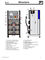
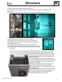
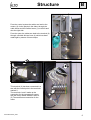
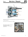
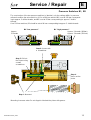
As it appears from the illustration, the
whole front door (1) can be removed by
turning both fasteners into horizontal
position.
The control system (2) is mounted at a
distance to the water tank so that neither
heat or cold is transferred from the tank to
the power module box.
The fans (4) of the motor provides the
cooling. They take air from the back of the
machine and press it forwards past the fins
of the motor and on to the space between
the water tank and the power module box.
The internal overflow pipe of the water tank
is connected to a rubber hose (3) which
leads the water to the floor if a fault should
arise in the control system.
Each motor is suspended in four rubber
dampers (5).
On the pressure outlet of the machine a
non-return valve (6) and a pressure
accumulator (7) are mounted.
4
5
7
DELTABOOSTER_GB01
3