1
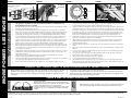
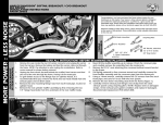
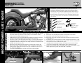
FIGURE 6
POSITION FRONT EDGE OF COLLECTOR HEAT SHIELD
AT REAR EDGE OF COLLECTOR COLLAR WELD
AND SLIDE FORWARD
ALIGMENT CLIP
HEAT SHIELDS SHOULD BE FLUSH
HEAT SHIELD CLIP
HEAD PIPE
COLLECTOR
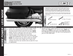
FIGURE 7
FIGURE 8
Installing
circlip
leave 1/16” gap
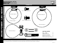
4. COLLECTOR HEATSHIELD
HEAD PIPE HEAT SHIELD
1. HEADER
COLLECTOR
3. TORCA BAND CLAMP
Protect with tape
Step 12 system install. (NOTE)
Flange
2. MUFFLER BODY
HOSE CLAMP
VANCE & HINES EXHAUST
SYSTEM INSTALLATION
SLIDE FORWARD AND DOWN (MAY REQUIRE SOFT MALLET)
COLLECTOR HEAT SHIELD
5. MUFFLER BODY HEATSHIELD
Note: Black Ceramic exhaust systems require special care during installation. Applying low tack
tape (painters or equivalent) to edges or areas where movement or scratching can occur
during installation can be very helpful.
1.
Attach mounting bracket 581-P to frame using two 3/8” x 3/4” flange head bolts (supplied) (Figure 2). NOTE:
If equipped, the plastic plugs must be removed
2.
Remove head pipes and heat shields from protective packaging. Place each heat shield on a non-abrasive
surface such as a blanket or carpet large enough to fully protect heat shields. Using a pencil, lightly mark the
outside edge of each heat shield to show location of mounting clips that hose clamps will loop. (Figure 3).
3.
Lay head pipes into their respective heat shields. Use care when installing the #24 and #20 hose clamps
to avoid damaging the coating; install by carefully feeding through the tail end of clamps. Install # 24 hose
clamps on the four heat shield clips located closest to the collector end of the heat shield. The #20 hose
clamps are inserted into the three other heat shield clips. (Figure 3). Take note of clamp screw head direction
(Figure 4). Screw head must be accessible when system is installed on motorcycle for adjustment purposes.
NOTE: To avoid excessive movement of heat shield during installation, only finger tighten at this time.
4.
Apply a small amount of anti-seize compound to the threads of the oxygen sensors and install them into the
new head pipe. NOTE: Install O2 sensor with the gray connector (short) into the front head pipe and the O2
sensor with the black connector (long) into the rear head pipe. Be careful not to get anti-seize on the snsor
tip, it may affect sensor function
5
Install exhaust port flanges and circlips (from stock system) onto head pipes (Figure 6). NOTE: Use care when
installing flanges, using a low tack tape (blue painters or equivalent) if necessary to protect the edges of the
heat shields from damage
6
Using stock flange nuts, carefully install head pipes into exhaust ports, starting with the rear cylinder.
Assistance may be required. NOTE: Do not tighten at this time.
7.
Slide the nut plate (supplied) into the bracket that is welded to the back side of the muffler. Loosely install two
5/16” flange head bolts (supplied) through 581-P bracket into nut plate.
8.
Install Torca band clamp with bolt facing down (supplied) onto end of muffler body (Figure 3 and 7).
9.
10.
11.
12.
13.
14.
15.
16.
17.
18.
19.
Install nut plate
Install collector heat shield onto header by sliding it on from the rear (Figure 5). NOTE: Do not force collector
heat shield directly onto header from the side, damage to collector heat shield will result. Attach collector
heat shield with two #24 hose clamps (supplied). NOTE: Finger tighten at this time.
Holding the muffler Body (D733RP) in a vertical position (large end down) slip the muffler body heat shield
(stamped D739HP) onto the muffler body from front to back and secure with a #44 hose clamp in the front
and a #56 hose clamp in the rear. (Figure 4) NOTE: Use care when installing heat shield to avoid damaging
the muffler body coating. Use a low tack tape (painters tape or equivalent) to protect the transition on the
muffler body (D730RC) between tapered section and 4.5” round end section during installation. Finger
tighten the hose clamps at this time to prevent the heat shield from excessive movement. (Figure 4).
Install muffler assembly onto collector of header assembly (Figure 7). Attach muffler assembly to installed
bracket and secure with 5/16” Flange head bolts (Supplied).
Tighten muffler body heat shield and leave about 1/16” even gap on the rear between heat shield and
muffler body (Figure 8). Make sure top edge of heat shield is aligned with centerline of muffler body to
maintain acceptable clearance.
Tighten the exhaust port flange nuts, nut plate bolts, Torca band clamp and 5/16” flange head bolts at the
bracket.
Tighten hose clamps securing header heat shields and collector heat shield making sure that they are flush.
(Figure 5)
Feed wire for the rear O2 sensor (Black) through the frame and under the seat. Re-install battery, plug the
sensor into the stock wiring connector.
Feed connector for the front oxygen sensor (Gray) through the frame and into the holder on the frame
behind rectifier. Plug the sensor into the stock wiring connector.
Tighten the floor board mounting bolts on models so equipped.
Be sure to tighten all hardware before starting your motorcycle.
After installation and before starting motorcycle, remove protective tape and completely clean pipes and
mufflers with warm soapy water and a clean soft cloth that will not leave a residue. NOTE: Any residue, oil, or
fingerprints will stain the chrome when the metal heats up.
EXHAUST CARE - HELPFUL HINTS TO AVOID DISCOLORATION OF EXHAUST SYSTEM
1.
When installing a new set of black pipes, make sure your hands are clean and free of oil. After
installation, thoroughly clean pipes with warm soapy water and a soft cloth. Dry with clean
towel to remove any residue before starting the motorcycle. Do NOT use anything abrasive to
clean pipes.
2.
3.
4.
Avoid long periods of idling as this can cause discoloration.
Intake leaks can cause the engine to run lean and overheat, this could lead to discoloration.
Make sure there are no exhaust leaks at the junction of the exhaust pipes and cylinder head.
We recommend replacing gaskets if they are worn.
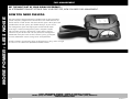
FUEL MANAGEMENT:
Take the guess work out of fuel injection with Fuelpak Fuel
Management. Contact your local dealer or call (562) 921-0071
to order. Visit fuelpakfi.com for more information.
Fuelpak is intended for racing or off-highway use only, and is
not legal for sale or use in California on pollution-controlled
vehicles.
QUIET
BAFFLE
VANCE & HINES OPTIONAL ACCESSORIES
FUELPAK
MORE POWER : LESS NOISE
FIGURE 5
Quiet baffle P/N 21904 is available for this system. The quiet baffle will lower
the sound level by 2-3db on average. Contact your local dealer to order.
PLEASE NOTE: Every effort is made for Vance & Hines Exhaust Systems to provide improved cornering clearance. However, due to design and space limitations on some motorcycle models, ground and
cornering clearance may not be improved and in some cases may be reduced. Be sure to follow proper installation instructions.
Page 2 of 4
D824IN Rev.1.1