1
INSTALLATION INSTRUCTIONS - SPRITEIMIDGET
FIVE SPEED OVERDRIVE TRANSMISSION CONVERSION KIT, MARK V
Perform the shop work required to do this installation using good shop safety and workmanship practices. Reference to a quali ty
SpritelMidget service manual will be required. Read these instructions fully before beginning work, then refer back as you work.
I.
PURCHASE MATERIALS
Purchase a five-speed transmission from an August 1979 thru 1982 Datsun 210. You can identify a correct transmission using
these factors :
Both the input and output shafts are 25/32" with 18 splines.
The serial number, stamped on a pad at the top, front of the bellhousing, just behind the engine cylinder head,
should start with the letter "F ' .
When you purchase the transmission also get: the gearshift lever, throw out bearing carrier and fork. If the car is to be used on the
street, without the optional speedometer ratio correcting adapter and cable, obtain the stock Datsun 210 speedometer cable and
housing.
You may use the original slave cylinder that is on the SpritelMidget, with modification. Or Rivergate can furnish a new, CNC
billet cut aluminum cylinder, with a stainless steel braid covered Teflon hose. This hose connects the master cylinder and slave
cylinder without any extra connections.
The original Datsun 210 slave cylinder cannot be used , as it is too small. It will cause pedal pressure to be too high and will cause
the pressure plate to over-travel.
II.
PREPARATION OF CAR
Remove engine, transmission and driveshaft. Be certain the center screw attaching the heater to the body above the center of the
bellhousing does not protrude downward where it will hit the transmission during installation. If the car's frame is bent upward in
the front, as many are, this will be an even tighter fit and the rear mount may also be tight. No modifications to the car body are
required.
ID.
PREPARE THE TRANSMISSION
Remove the starter, clutch, flywheel and engine rear plate. Inspect the two locator pins in the rear of the engine blOCK, one at the
top center and one below the oil pump. Be sure they are present and in good, straight condition. Straighten and file or replace as
needed .
Remove the oil pump cover from the engine rear plate . Occasionally, on early engines, this may require heating, as these early
engines had the cup soldered in . Be careful not to damage the cup.
Bolt the adapter plate to the front ofthe transmission, using only one of the 5/16" x 2-114" cap screws at each side to hold in place. .
The side with the counter sunk holes fits toward the transmission. This allows you to mark the spots to modify for oil pump cover
and starter drive clearance.
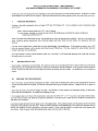
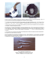
. Look back through the hole for the oil pump cover in the adapter plate. Using a felt tip marker, mark the portion of the front ofthe
transmission that protrudes into this circle. Mark the starter protrusion on the bellhousing to cut a starter drive clearance hole as
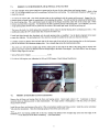
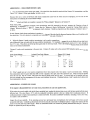
follows (not needed if you have converted to a gear drive starter). Center a felt tip marker in the starter hole in the adapter plate
(See Photo). Mark the point inside the bellhousing that aligns with the center of this hole .
1
....
~_.a.~v
.
_ _ ......, .,........_ ,
....
~ -...
.....OJ..,............
-- _ .
•
-- - - - -
-
-
- - - -- -
- - - - 0- --- --- - -
0 - - - - -- -- - ."
.I
.
_
.
_
_