1
COMPONENT SERVICE
B.
F10X-SERIES SERVICE MANUAL
FEBRUARY 2012
LIFT ACCESS FOR SERVICE
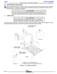
Refer to Figure 4-1. Platform and lifting frame components can be accessed by deploying the travelling frame. Some
components within the carriage can be accessed from the front of the carriage when it is deployed. Other components
within the carriage, or inside the enclosure, must be accessed from the top of the enclosure. Some of these components may require repositioning of the carriage to allow access through the openings between the enclosure supports.
These four supports, which tie the top flanges of the side channels together, are fastened in place. They can be removed for greater access.
ENCLOSURE SUPPORTS
TRAVELLING FRAME
LEFT
FRONT
REAR
SERVICE ACCESS AREA
RIGHT
RSM0033001
FIGURE 4-1: SERVICE ACCESS AREA (TOP VIEW)
C.
TRAVELLING FRAME
Refer to Figure 4-2. The platform, lifting frame, and carriage are referred to as a “travelling frame” when assembled as
a unit. This assembly locates on two rails inside the enclosure, and is able to move in and out of the enclosure.
The travelling frame should be removed from the enclosure by first separating the platform from the lifting frame, and
then separating the lifting frame from the carriage. The carriage is then removed from the enclosure. This is the preferred approach because it avoids having to cope with the heavy weight of the assembled travelling frame.
Procedures describing the removal of the platform, lifting frame, and carriage are in the following sections.
PLATFORM
LIFTING FRAME
TRAVELLING FRAME
CARRIAGE
ENCLOSURE
RSM0033101
FIGURE 4-2: TRAVELLING FRAME
4-2
32DF1002.B.1