1
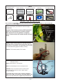
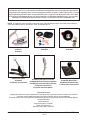
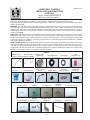
7/16”,15mm(short),
16mm(short), 13mm,
11mm Wrench
TOOLS
Ratchet / Extension
Pliers
7/16” , 9/16”, 13mm Socket
Electrical Tape
Clean Rags
Teflon® Tape
Loctite®
Wire Stripper/Crimper
Plastic Trim Tool
BRAKE LINE INSTALLATION
NOTE: ARROW SIGN (
) INDICATES LOCATION OF FRONT OF VEHICLE WITH RESPECT TO THE PICTURE VIEW.
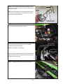
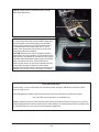
STEP 1. Identify the mounting location of solenoid and the
Master Cylinder (M.C) front brake line within the engine
compartment.
Mounting Location
Master Cylinder
Front Brake Line
Important! This kit will only work for SRT8 models.R/T
models can only partially turn off Traction Control
(ESP). Unless the car was modified to completely
remove Traction Control, R/T models should not install
this kit.
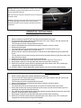
Hydraulic Control
Unit (HCU)
Fuse Box
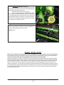
STEP 2. Attach mounting bracket to solenoid as shown.
Add a few drops of Loctite® (red) to bolt threads. Place one
1/4-20 bolt, 1/4” flat washer, 1/4” lockwasher, and 1/4-20 nut
on each hole and fully tighten to 20Nm (15 ft-lbs).
TOOLS: 7/16” wrench, ratchet, 7/16” socket
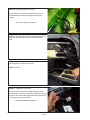
STEP 3. Tighten the provided adapters and plugs to
solenoid as shown.
TOOLS: 16mm Wrench, 11mm Wrench
To Master Cylinder
Front Brake Line
NOTE: Use Teflon® tape to ensure a leak-proof seal.
Solenoid Nut
To HCU
Plugged
CAUTION: Using an excessive amount of thread sealer
can contaminate the solenoid valve or brake system.
Use tape sparingly.
If solenoid body loosens while tightening adapters/
plugs. First, make sure ports are correctly aligned and
then use a 9/16”socket to re-tighten top solenoid nut.
HURST PERFORMANCE
CHATSWORTH, CA
2/10
www.HURST-SHIFTERS.com