1
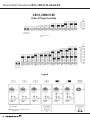
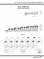
Dismantling Procedures CR-H, CRN-H 32•45•64•90
8
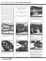
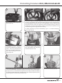
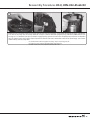
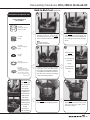
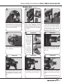
Pos. 105
Cartridge Seals
Will lift out as a complete assembly.
9
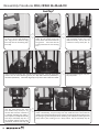
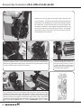
To remove the motor stool (Pos. 1a) and motor: If needed, place a block under the Support
Bracket (Pos. 90c). Loosen and remove the Allen Screws (Pos. 28) connecting the motor
stool to the pump head. Leave the motor stool attached to the motor and/or bearing
flange to protect the motor shaft and bearing flange shaft. Loosen the Slide Rail (Pos.
90d) connecting the motor to the Base (Pos. 90), then slide the motor backward on the
base. If sliding provisions are not available on the base or when working on Cool-Top
and Back-to-Back models, use a lifting device to lift and remove the motor assembly
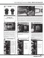
10
11
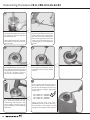
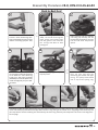
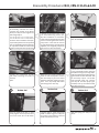
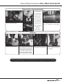
All models requiring full dismantling
for STACK® (Pos. 80) replacement:
Loosen but do not remove the 24 mm
Staybolt Nuts (Pos. 36). Then, proceed
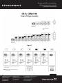
to Dismantling, step 40. For Back-toBack inboard seal change, continue
by first placing blocking under the
staybolts. Then, remove the Staybolt
Nuts, Washers (Pos. 66a) and Support
Plate (Pos. 90c).
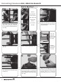
Remove the outermost Pump Head
(Pos. 2b). This may require light blows
with rubber mallet to the underside of
the pump head.
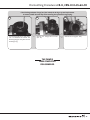
To remove the Outer Sleeve (Pos. 55a),
diagonally grip the Staybolts (Pos. 26).
Use your thumbs to press against the
sleeve to release the sleeve from the
middle pump head. If it does not move
freely, light blows with a rubber mallet
may be required. Once loose, remove
the sleeve.
13
14
15
Back-to-Back Seal
Back-to-Back Seal
Back-to-Back Seal
12
Back-to-Back Seal
Back-to-Back Seal
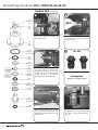
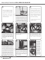
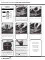
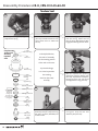
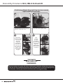
To remove the
Inboard Shaft
Seal (Pos. 105b)
Remove the
loosen, but do
Spring
Remove O-ring
not remove, the
(Pos. 108b),
(Pos. 107b),
two 3 mm
and Spring/
and Seal Driver
Set screws
O-ring Cup
(Pos. 111b).
(Pos. 113a) in
(Pos. 106b).
the Seal Driver
( Pos. 112). Slide
the seal driver
off of the shaft.
3