1
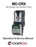
CRX Card Reader
Generic Interface - Programmer’s Guide
Table of Contents
Limited Warranty................................................3
Disclaimer...........................................................3
6.4.1 Buzzer Commands.........................11
6.4.2 LED Commands.............................11
6.4.3 System Commands........................12
Section 1: General Information
Introduction...........................................................4 Section 7:Controlling the CRX Module
7.0 Controlling the Module.................................13
7.1 CRX/CCTPS Power-up (Default Settings)...13
7.2 CCTPS Awaiting Card Swipe.......................13
7.3 CCTPS Not Ready.......................................14
Section 3: Features
3.1 Magnetic Swipe Card Reader........................4 7.4 CRX Card Swipe..........................................14
3.2 LCD Display....................................................4 7.5 CCTPS Approves Card................................15
3.3 Built in Audible Buzzer...................................4 7.6 CCTPS Denies Card....................................15
3.4 LED Indicator..................................................4 7.7 Product Selection.........................................16
3.5 RS-232 or 0V to 5V TTL Serial Interface.......4 7.8 Transaction Complete..................................16
3.6 Cancel Credit Button......................................4 7.9 CRX Cancel Credit.......................................16
3.7 Reverse Swipe Button...................................4 7.10 Selection Timeout.......................................17
Section 2;
Numeric and Data Formats...............................4
Section 8: Coinco CRX Preferred OperatinG
States
8.0 Preferred Operating States..........................18
Section 4: Hardware Interface Requirements
4.1 Power.............................................................5
4.2 Communications............................................5
4.2.1 Serial Interface.................................5 Section 9: Additional References
4.2.2 Four Wire Hardware Interface..........5 References........................................................19
4.2.3 Cabling.............................................5
Section 5:CRX Interface Protocol
5.1 Magnetic Card Data.......................................6
5.1.1 ASCII................................................6
5.1.2 RAW.................................................6
5.1.3 Card Data Handshake.....................6
5.2 Cancel Button................................................6
5.3 Swipe Button..................................................6
5.4 CRX Command Format......................7
5.4.1 Header..............................................7
5.4.2 Data.................................................7
5.4.3 Checksum........................................7
5.4.4 Command Handshake.....................7
Section 6: Command Set
6.0 Command Set................................................8
6.1 Display Commands........................................8
6.1.1 LCD Commands...............................8
6.1.2 LCD Cursor Commands...................9
6.2 Display Data Commands...............................9
6.3 Card Reader Commands.............................10
6.4 Interface Commands...................................10
LIMITED WARRANTY
EXCEPT AS SPECIFICALLY STATED IN THIS AGREEMENT, THE SOFTWARE IS PROVIDED AND
LICENSED “AS IS” WITHOUT WARRANTY OF ANY KIND, EITHER EXPRESS OR IMPLIED, INCLUDING BUT NOT LIMITED TO, THE
IMPLIED WARRANTIES OF MERCHANTABILITY,
FITNESS FOR A PARTICULAR PURPOSE AND NONINFRINGEMENT. FURTHER, COINCO DOES
NOT WARRANT THE ACCURACY, COMPLETENESS, PERFORMANCE, CURRENCY OR THAT
THE SOFTWARE IS ERROR-FREE.
Coinco does warrant, however, that the Software media shall be free of defects in workmanship for a
period of ninety (90) days from the Coinco’s delivery of, or provision of access to, the Software to You.
During this ninety (90) day period, Coinco will replace at no cost to You any such defective media returned to Coinco, postage prepaid. This media replacement is and shall be Coinco’s sole liability and
your sole and exclusive remedy under this limited warranty.
IN NO EVENT SHALL COINCO BE LIABLE TO YOU OR ANY OTHER PERSON OR ENTITY FOR
ANY DAMAGE CAUSED IN ANY PART BY YOUR USE OF THE SOFTWARE OR YOUR RELIANCE
ON THE INFORMATION CONTAINED IN THE SOFTWARE.
DISCLAIMER
LICENSE FEES FOR THE SOFTWARE DO NOT INCLUDE ANY CONSIDERATION FOR ASSUMPTION OF RISK BY COINCO, AND COINCO DISCLAIMS ANY AND ALL LIABILITY FOR DIRECT,
INDIRECT, SPECIAL, INCIDENTAL, CONSEQUENTIAL, PUNITIVE OR ANY OTHER DAMAGES
ARISING OUT OF THE USE OR OPERATION OF OR INABILITY TO USE THE SOFTWARE, OR
ANY LIABILITY, CLAIMS, JUDGMENTS, DAMAGES AND EXPENSES (COLLECTIVELY, “CLAIMS”)
CAUSED BY YOUR USE, REPRODUCTION, DISTRIBUTION OR PROVISION OF ACCESS TO
THE SOFTWARE OR BREACH OF THE TERMS OR CONDITIONS OF THIS AGREEMENT, EVEN
IF COINCO HAS BEEN ADVISED OF THE POSSIBILITY OF SUCH DAMAGES. FURTHERMORE,
YOU AGREE TO INDEMNIFY COINCO AND TO HOLD COINCO HARMLESS FROM SUCH CLAIMS
Coin Acceptors, Inc
300 Hunter Avenue
Saint Louis, MO 63124
Copyright © 2007 Coin Acceptors, Inc.
All rights reserved.
3
Section 1 - Section 3: Introduction, Numeric & Data Formats, & Features
1.0
INTRODUCTION
The CRX Programming Guide contains the
hardware interface requirements, communication
protocol, command sets, and Coinco’s preferred
operation of the BillPro and MC Series CRX card
reader modules when connected to a credit card
transaction processing system (CCTPS). This
guide is intended for engineers, software developers and system integrators wishing to interface
the Coinco CRX card reader with a credit card
transaction processing system.
2.0
NUMERIC AND DATA FORMATS
Within this document the following numeric and
data formats are used to represent hexadecimal
numbers, binary numbers, and ASCII character
bytes.
•
•
•
•
•
Hexadecimal numbers will be preceded
with a “0x”, i.e. 0x01, 0xff.
Binary numbers will be terminated with a
“b”, i.e. 0101b, 10b.
All other numbers are assumed to be
decimal.
ASCII character bytes are
identified by placing the byte value
between the less than < and > greater
than characters.
3.0
FEATURES
3.1
Magnetic Swipe Card Reader
•
Bidirectional ISO card reader
Reads track 1 and track 2 encoded data
that meets the ANSI (American Standards
Institute) and ISO (International Standards
Organization) standards.
•
Programmable track enable\disable
•
ASCII or RAW card data transmission.
3.2
LCD Display
•
•
2 Line x 16 character backlit display
Programmable display and cursor control
3.3
Built-in Audible Buzzer
•
Selectable duration, beeps, and tone.
3.4
LED Indicator
•
Selectable duration and blinks.
3.5
RS-232 or 0V to 5V TTL Serial Interface
•
Selectable TTL or RS-232 signal levels
via CRX harness.
3.6
Cancel Credit Button
3.7
Reverse Swipe Button
LRC indicates the calculated logical
redundancy checksum byte
4
Section 4: Hardware Interface Requirements
4.0
HARDWARE INTERFACE REQUIREMENTS
4.1
Power
•
5VDC +/- 10%; 0.15a max current draw
4.2
Communications
4.2.1
•
•
•
•
•
•
4.2.2
•
•
•
•
4.2.3
Serial Interface
9600 Baud
8 Data Bits
No Parity
1 Stop Bit
Full Duplex
Transmits and Receives at RS-232 or 0 to 5 VDC TTL Signal Levels.
Four Wire Hardware Interface
Ground
Interface Module Receive
Interface Module Transmit
+5VDC Required External Power Source
Cabling
TTL (Not available on MC-CRX versions)
Pin 1 – Ground
Pin 2 – RX (5VDC)
Pin 3 – TX (5VDC)
Pin 4 – +5VDC
RS-232 (Available on BillPro-CRX & MC-CRX versions)
Pin 1 – NC
Pin 2 – RX (5VDC)
Pin 3 – TX (5VDC)
Pin 4 – NC
Pin 5 – Ground
Pin 6 – +5VDC
Pin 7 – NC
Pin 8 – NC
Pin 9 – NC
5
Section 5:CRX Interface Protocol
5.0
CRX INTERFACE PROTOCOL
5.1
Magnetic Card Data
The CRX module is capable of transmitting card
data as either an ASCII text stream or as RAW
data from the magnetic head. The module will
transmit card data after any card swipe independent of the operating state of the credit card
transaction processing system.
5.1.1
ASCII
Normal operation mode the CRX module decodes the magnetic head data and converts the
data to an ASCII text stream. During the decoding process the module checks for any data errors in the data received from the magnetic head,
if any errors occurred, the start sentinel and end
sentinel with checksum will be transmitted without
card data for track 1 and/or track 2. Otherwise,
the card data will be transmitted as a financial
transaction card for up to two tracks.
Inter byte time must be less than 20 ms. Exceeding the inter byte time is assumed to be the end
of transmission.
5.1.2
RAW
The CRX will enter RAW data mode on receipt
of the ENTER RAW DATA MODE card reader
command. The unit will stay in RAW data mode
until the power is reset or the module receives
the RESET interface command or EXIT RAW
DATA MODE command from the card transaction
module.
RAW data is transmitted to the card transaction
module one byte at a time filling bit 7 through 0 of
the data byte on receipt of each bit from the magnetic card reader head. No decoding or validity
testing of the data is preformed.
Inter byte time must be less than 20 ms. Exceeding the inter byte time is assumed to be the end
of transmission.
5.1.3
Card Data Handshake
The credit card transaction processing system
will implement a handshake on the received data
by sending an ACK (0x06) within 20ms of detecting the end of transmission. If the CRX module
does not receive an acknowledgement within
40ms of sending the last character in the string, it
will re-transmit the string. The module will make
3 attempts to transmit the card data before dropping the card data.
5.2
Cancel Button
The CRX module transmits the following Cancel
Button code to the credit card transaction processing system anytime the module’s Cancel
Credit Button is pressed. The Cancel Button
data consists of three bytes of data representing
the interface header byte <0xC1>, cancel command <0x51>, and LRC checksum.
Cancel Credit Button String =
<0xC1><0x51><LRC>
LRC = 0xC1 xor 0x51 = 0x90
5.3
Swipe Button
The CRX module transmits the following Swipe
Button code to the credit card transaction processing system anytime a valid card swipe occurs from a reverse card swipe (bottom to top of
reader) when the bill acceptor is positioned in an
up stack configuration. The Swipe Button data
consists of three bytes of data representing the
interface header byte <0xC1>, swipe button command <0x52>, and LRC checksum. The Swipe
Button data will precede the transmission of any
card track data.
Swipe Button String = <0xC1><0x52><LRC>
LRC = 0xC1 xor 0x52 = 0x93
6
Section 5: CRX Interface Protocol
5.4
CRX Command Format
The CRX module command format consists of a
header byte, up to 40 data bytes, and a checksum byte. The header, data and checksum bytes
are transmitted to the CRX module as ASCII
character bytes.
Each command has the following format:
<header><data><data>….<data><checksum>
Below is a description of each component of the
CRX command format.
5.4.1
Header
The <header> byte identifies the CRX command
type and number of data\command bytes to follow. The two most significant bits identify the
command type and the lower six bits indicate the
number of data bytes following the header byte
and preceding the checksum byte.
•
Bits 6 & 7 Identifies the command type to
the CRX unit.
o
o
o
o
•
00b = Display Command
01b = Display Data
10b = Card Reader Command
11b = Interface Command
Bits 0 - 5 Identifies the number of data/
command bytes to be received (doesn’t
include the header or checksum). The
module is capable of receiving a maximum
of 40 data bytes.
Examples:
1.
The following header byte represents a
Display Data Command with 8 bytes of
data.
01001000b
01001000b
Bits 7-6
Bits 5-0
01001000b = 0x48
7
Command Type 01 = Display Data
Number of Data Bytes 001000 = 8 Data bytes
2.
The following header byte represents a
Interface Command with 1 command byte.
11000001b Bits 7-6 Command Type 11 = Interface Command
11000001b Bits 5-0 Number of Data Bytes 00000 = 1 Data Byte
11000001b = 0xC1
5.4.2
Data
The <data> portion of the command format may
contain up to 40 bytes of specific CRX commands for controlling the operation and configuration of the unit or display text for the CRX liquid
crystal display.
5.4.3
Checksum
The <checksum> is a one byte LRC calculated by
XORing the header byte with each data byte.
5.4.4
Command Handshake
The CRX Module implements a simple handshake of received data by acknowledging data
received that passes the integrity check with an
ACK (0x06). The ACK must be transmitted within
40ms of receiving the checksum and any transmission not acknowledged within the specified
timeout should be re-transmitted.
Section 6: Command Set
6.0 COMMAND SET
The CRX command set consists of commands to control the various hardware functionality of the
CRX module. The commands are divided into four categories: Display, Display Data, Card Reader,
and Interface Commands. An in-depth description of each command category is provided below with
the associated command tables identifying the command name, hex value, and description. The
command hex value must be converted to the associated ASCII character for transmission to the
module.
6.1
Display Commands
The Coinco CRX module supports the following LCD commands to control the cursor and display.
6.1.1
LCD Commands
The Card Transaction Module is responsible for all aspects of the display except initialization. Within
the first second after power up or reset the CRX Module will reset the display and execute the LCD
initialization sequence. The credit card transaction processing system should not send display commands or data during this time.
Each “data” portion of a display command is immediately forwarded to the display as an instruction
byte. Multiple display instructions may be contained in the display command string.
Commands
Value
Clear Display
Blank Display
Restore Display
Scroll Display Left
Scroll Display Right
0x01
0x08
0x0c
0x18
0x1c
Example:
Description
Erases display and returns cursor to home position
Turns Display Off (without clearing data)
Turns Display On (with cursor hidden)
Shifts display one character left (all lines)
Shifts display one character right (all lines)
Blank Display =< 0x01>< 0x08> < LRC>
8
Section 6: Command Set
6.1.2
LCD Cursor Commands
The CRX module’s cursor commands control the LCD’s cursor type, visibility, and position of the cursor on the LCD.
Commands
Value
Description
Cursor Home
Cursor On
Cursor Off
Cursor Blink
Cursor Move Left
0x02
0x0e
0x0c
0x0d
0x10
Returns cursor to upper left corner of display
Turns on visible underline cursor
Turns off visible underline or blinking cursor
Turns on visible blinking-block cursor
Move cursor one character left
Cursor Move Right
0x14
Mover cursor one character right
Set Cursor Position
0x80 + address
Set Cursor Position
to Line 1
Set Cursor Postion
to Line 2
0x80
Moves cursor to the specified address 0x80 to 0x8F
and 0xCO to 0xCF
Sets cursor position to start of line 1
0xc0
Sets cursor postition to start of line 2
Example1:
Cursor Home =< 0x01>< 0x02> <LRC>
The cursor can be positioned anywhere on the screen by sending the proper instruction. To position
the cursor, send the set-position byte value. For example, to move to line 2, position 5, send <0xc4>.
The following table shows cursor position decimal addresses on the LCD.
Line 1
1
2
8
1
2
9
1
3
0
1
3
1
1
3
2
1
3
3
1
3
4
1
3
5
1
3
6
1
3
7
1
3
8
1
3
9
1
4
0
1
4
1
1
4
2
1
4
3
1
9
2
1
9
3
1
9
4
1
9
5
1
9
6
1
9
7
1
9
8
1
9
9
2
0
0
2
0
1
2
0
2
2
0
3
2
0
4
2
0
5
2
0
6
2
0
7
Line 2
Example2:
6.2
Sets the cursor position to the last character on line 1 of the LCD.
Set Cursor Position = <0x01><0x8F><LRC
Display Data Commands
The display data command writes the ASCII <data> bytes contained in this command string to LCD
starting at the current cursor position of the LCD. The CRX LCD is a two line by sixteen character
display.
The CRX module may not be capable of responding to display commands while processing magnetic
stripe data. Therefore, the credit card transaction processing system must allow a non-response
timeout of 3 seconds. If the module fails to respond to display data within the timeout period, the
9
Section 6: Command Set
credit card transaction processing system should reset the CRX module.
During periods of inactivity the credit card transaction processing system should refresh the display
on a regular interval.
Example1:
6.3
Displays two characters of data at the current LCD cursor position.
Display Data = <0x42> <data> <data>< LRC>
Card Reader Commands
The CRX Card Reader Commands control the format of the magnetic card data and which card
tracks will be transmitted on a card swipe.
Commands
Value
Enter Raw Data Mode
0xe5
Exit Raw Data Mode
Enable Track 1
Enable Track 2
Enable Track 1 & Track 2
0xe6
0xe9
0xea
0xeb
6.4
Description
Transmits Enabled Card Track Data in RAW format
starting with the first bit received
Transmits Enabled Card Track Data in ASCII format
Enables the transmission of only Track 1 Data
Enables the transmission of only Track 2 Data
Enables the tramsmission of Track 1 & Track 2 Data
Interface Commands
The Coinco CRX module supports the following interface command set to control the buzzer, LED,
and system operation.
10
Section 6: Command Set
6.4.1 Buzzer Commands
The Buzzer Interface commands control the operation of the CRX buzzer. The buzzer commands
are used to indicate various states or errors during the processing of the card data and vending operations.
Commands
Value
Description
Turn on Buzzer
Beep Buzzer Once
Beep Buzzer 2 Times
Beep Buzzer 3 Times
Beep Buzzer 4 Times
0x20
0x21
0x22
0x23
0x24
Turns on continuous buzzer (no beeps)
Beeps buzzer 1 Time at selected tone and rate
Beeps buzzer 2 Times at selected tone and rate
Beeps buzzer 3 Times at selected tone and rate
Beeps buzzer 4 Times at selected tone and rate
Beep Buzzer 5 Times
0x25
Beeps buzzer 5 Times at selected tone and rate
Beep Buzzer 6 Times
0x26
Beeps buzzer 6 Times at selected tone and rate
Turn on Beeper
0x27
Beeps buzzer continuously at specified rate and tone
Select Beeper Tone 1
0x28
Changes beeper tone to tone 1 (defined by config data)
Select Beeper Tone 2
0x29
Changes beeper tone to tone 2 (defined by config data)
Select Beeper Tone 3
0x2a
Changes the beeper tone to tone 3 (defined by config data)
Select Beeper Rate Slow
0x2b
Sets the Beeper rate to slow
Select Beeper Rate
Normal
Select Beeper Rate Fast
0x2c
Sets the Beeper rate to normal
0x2d
Sets the Beeper rate to fast
Turn off Buzzer
0x2f
Turns off continuous buzzer or beeper
Example1:
6.4.2
Beep Buzzer Once =< 0xC1>< 0x21>< LRC
LED Commands
The LED Interface commands control the operation of theCRX module’s LED. The LED commands
are used to indicate various states or errors during the processing of the card data and vending operations.
11
Section 6: Command Set
Commands
Value
Turn on LED
Blink LED Once
Blink LED 2 Times
Blink LED 3 Times
Blink LED 4 Times
0x40
0x41
0x42
0x43
0x44
Turns on the LED
Blinks the LED once
Blinks the LED 2 Times
Blinks the LED 3 Times
Blinks the LED 4 Times
Blink LED 5 Times
0x45
Blinks the LED 5 Times
Blink LED 6 Times
0x46
Blinks the LED 6 Times
Blink LED
0x47
Starts continuous blinking the LED at specified rate
Select Blink Rate Slow
0x4b
Sets the blink rate to slow
Select Blink Rate Normal
0x4c
Sets the blink rate to normal
Select Blink Rate Fast
0x4d
Sets the blink rate to fast
Turn Off LED
0x4f
Turns Off the Led (blinking or otherwise)
Example:
6.4.3
Description
Blink LED = <0xC1> <0x47>< LRC>
System Commands
The unit can receive the following System Commands.
Commands
Software Version
Reset
LED
Example:
Value
0xe0
0xef
0xed
Description
Sends CRX software version
Resets the CRX unit
Used to turn on all segments of the LCD display
Reset = <0xC1> <0xef>< LRC>
Software Version
The software version will be transmitted to the transaction module on receipt of the Software Version
Diagnostic Command.
CRX Software Version = <Mfg Id><S/W Identifier>”-“<S/W Revision Number>
•
•
•
•
Mfg Id
S/W Identifier
Separator
S/W Revision
Manufacturer of theCRX module
Software ID Number (5 digits)
Version and Revision Separator (1 character)
S/W Identifier Revision Number (2 digits)
“CAI”
“67251”
“-“
“03”
Reset
The Reset command performs a software reset of the CRX module.
12
Section 7: Controlling the CRX Module
7.0
CONTROLLING THE CRX MODULE
The following sections describe the operation of the CRX module in conjunction with a Credit Card
Transaction Processing System (CCTPS). The tables below describe the actions performed by the
CRX and CCTPS during typical card reader operational states.
7.1
CRX/CCTPS Power-up (Default Settings)
CRX
CCTPS
Power Up
Enables ASCII card data transmission
Enables magnetic card reader tracks 1 & 2
Blinks LED five times
Beeps buzzer five times
Power up
Displays Coin Acceptors and software
version message on the LED
Waits for command for the CCTPS
Receive Software Version Command
Send Software Version
Send Interface Command Software Version to verify
CRX is Attached and Operational
Receive Software Version
Determine CCTPS Card Processing State
If CCTPS Ready to Process Card Data go to CCTPS
Awaiting Card Swipe
If CCTPS Not Ready to Process Card Data go to
CCTPS Out of Service Cash Only
7.2
CCTPS Awaiting Card Swipe
CRX
Receives LED ON command
Sends ASCII character ACK 0x06
Turns on LED
Receives LED Display Command
CCTPS
CCPTS Ready to Process Card Data
Sends LED ON command to CRX
Send “Please Swipe Card” message to CRX LCD
display using the Display Data Command
Sends ASCII character to ACK 0x06
Displays LCD Swipe Card Message
Wait for CRX Card Swipe
13
Section 7: Controlling the CRX Module
7.3
CCTPS Not Ready
CRX
CCTPS
CCPTS Ready to Process Card Data
Sends LED OFF command to CRX
Sends ASCII character to ACK 0x06
Turns LED OFF
Receives LCD Display Command
Sends “Cash Only” message to CRX LCD display using the Display Data Command
Sends ASCII character to ACK 0x06
Displays the LCD Cash Only message
Wait for CTTPS system to become Ready
7.4
CRX Card Swipe
CRX
Receives a valid card swipe
Transmits Card Data to CCTPS
Receives Fast Beep Rate Command
Sends ASCII character to ACK 0x06
CCTPS
Receives Card Data
Sends ASCII character to ACK 0x06 to CRX
Sends Fast Beep Rate Command to CRX
Beeps Buzzer Once
Receives LED Slow Rate Command
Sends LED slow rate command to CRX
Sends ASCII character to ACK 0x06
Receives LED continous blink command
Send LED continuous blink command to CRX
Sends ASCII character to ACK 0x06
Blinks LED Continuously
Receives LCD Display Command
Send “Authorizing” message to CRX LCD display using the Display Data Command
Sends ASCII character to ACK 0x06
Displays LCD Authorizing Message
Approves Card go to CCTPS Approves Card
Denies Card go to CCTPS Denies Card
14
Section 7: Controlling the CRX Module
7.5
CCTPS Approves Card
CRX
Receive Fast Beep Rate Command
Sends ASCII character to ACK 0x06
Receive Single Beep Command
Sends ASCII character ACK 0x06
Receive Fast LED Rate Command
CCTPS
Approves Card
Sends Fast Beep Rate Command
Sends single beep command to CRX
Sends LED blink fast rate command to CRX
Sends ASCII character to ACK 0x06
Receive LED Continuous Blink Command
Sends LED continuous blink command to CRX
Sends ASCII character to 0x06
Receive Make Product Selection Message
Send “Make Product Selection” message to the CRX
LCD display using the Display Data Command
Displays Product Selection Message
Waits for the CRX Cancel Credit, Product Selection,
or Transaction Timeout
7.6
CCTPS Denies Card
CRX
Receive Fast Beep Rate Command
Sends ASCII character to ACK 0x06
Receive Fast LED Rate Command
Sends ASCII character ACK 0x06
Receive three beep Command
CCTPS
Denies Card
Sends Fast Beep Rate Command
Sends LED fast rate command to CRX
Sends three beep command to CRX
Sends ASCII character to ACK 0x06
Receive three blinks command
Sends LED three blinks command to CRX
Sends ASCII character to 0x06
Beeps buzzer and blinks LED three times
Receive Invalid Card Message
Send “Invalid Card Message” message to the CRX
LCD display using the Display Data Command
Display Invalid Card Message
Return to CCTPS Awaiting Swipe Card
15
Section 7: Controlling the CRX Module
7.7
Product Selection
CRX
CCTPS
Receive Product Selected Message
Send “Product Selected” message to the CRX LCD
display using the Display Data Command
Sends ASCII character ACK 0x06
Displays Product Selected Message
Receive Fast Beep Rate Command
Sends ASCII character ACK 0x06
Receive Beep Once Command
Sends Fast Beep rate command to CRX
Sends Interface Command Beep Once to CRX
Sends ASCII character ACK 0x06
Beep one time
Waits for Product Selection, Cancel Credit, or Transaction Timeout
7.8
Transaction Complete
CRX
CCTPS
Receive Transaction Message
Send “Transaction Completed” message to the CRX
LCD display using the Display Data Command
Sends ASCII character to ACK 0x06
Displays Transaction Complete Message
Return to CCTPS Awaiting Swipe Card
7.9
CRX Cancel Credit
CRX
CCTPS
Sends Cancel Credit Command to CCTPS
Receives Fast Beep Rate Command
Sends ASCII character to ACK 0x06
Sends ASCII character to ACK 0x06
If CCTPS is in the CCTPS approves card state then
CCTPS should clear any remaining credit and end
transaction
Send Interface Command Set Beep Once to CRX
Receives Beep Once Command
Beep Once
Receives LED OFF Command
Send Interface Command LED OFF to CRX
Sends ASCII character to ACK 0x06
Turn LED OFF
Go to Transaction Complete
16
Section 7: Controlling the CRX Module
7.10
Selection Timeout
CRX
Receive LED Medium Blink Rate Command
Sends ASCII character to ACK 0x06
Receive Beep Medium Rate Command
CCTPS
If CCTPS is in the CCTPS Product Selection State
then CCTPS should clear any remaining credit and
end transaction
Send Interface Command LED Medium Blink Rate
Command to CRX
Send Interface Command Set Beep Medium Rate to
CRX
Send ASCII character to ACK 0x06
Receive Beep 2 Times Command
Send interface command Beep 2 Times
Send ASCII character to ACK 0x06
Receive Blink 2 Times Command
Send Interface command Blink LED 2 Times
Send ASCII character to ACK 0x06
Beep and Blink 2 Times
Receive LED OFF Command
Send Interface command LED OFF
Sends ASCII character ACK 0x06
Turn LED OFF
Return to CCTPS Swipe Card State
17
Section 8: Coinco CRX Preferred Operating States
8.0
COINCO CRX PREFERRED OPERATING STATES
The table below describes the typical operating states of a credit card transaction processing system
and the preferred operation of the CRX module while in each of these states. The table contains a
listing of the different states and the associated state of the module’s LED and Beeper. Each state
contains a list of commands that can be implemented by the credit card transaction processing system to place the CRX in the preferred mode of operation while in the described state.
State
LED
Beeper
Please Swipe Card
LED On
Beeper Off
Authorizing Transaction
Card Swiped-Data Sent
to Transaction Server
“NOT APPROVED”
LED blinks show
LED fast blinks 3
times
Commands
0xC1+0x40+LRC
0xC1+0x2F+LRC
Beeper Off
0xC1+0x4B+LRC
0xC1+0x47+LRC
0xC1+0x2F+LRC
Beeper beeps 3
times fast rate
0xC1+0x4D+LRC
0xC1+0x43+LRC
0xC1+0x2D+LRC
0xC1+0x23+LRC
Card Swiped-Data Sent
to Transaction Server
“APPROVED”
LED fast blink 1
time
Beeper beeps 1
time fast rate
0xC1+0x4D+LRC
0xC1+0x41+LRC
0xC1+0x2D+LRC
OxC1+0x20+LRC
Waiting on Product
Selection
LED blinks slow
Beeper Off
0xC1+0x4B+LRC
0xC1+0x40+LRC
0xC1+0x2F+LRC
Product Selection
Mode
LED blinks slow
Beeper beeps 1
time medium rate
Cancel Credit-Received
by Credit Card Transaction Server
LED is turned off
Beeper beeps 1
time fast
Transaction Timeout
LED is turned off
Beeper beeps 2
times at medium
rate
Out of service
LED is off
No beeper
0xC1+0x4B+LRC
0xC1+0x40+LRC
0xC1+0x2C+LRC
0xC1+0x20+LRC
0xC1+0x4F+LRC
0xC1+0x2D+LRC
0xC1+0x21+LRC
0xC1+0x4F+LRC
0xEC+0x2C+LRC
0xEC+0x22+LRC
0xC1+0x4F+LRC
0xEC+0x2f+LRC
18
9.0
ADDITIONAL REFERENCES
“BillPro -CRX MDB Bill Acceptor Card Reader Combo – Service and Operation Manual”, Coin Acceptors, Inc. 2006
“MC-CRX MDB Bill Acceptor Card Reader Combo-Operation and Service Manual”, Coin Acceptors,
Inc. 2007
“Identification Card - Physical Characteristics”, American National Standards Institute, ANSI/ISO/IEC
7810-1995
“Identification Cards - Recording Technique – Part 1: Embossing”, American National Standards Institute, ANSI/ISO/IEC 7811-1-1995
“Identification Cards - Recording Technique – Part 2: Magnetic Strip”, American National Standards
Institute, ANSI/ISO/IEC 7811-2-1995
“Identification Cards - Recording Technique – Part 4: Read-Only Magnetic Tracks 1 and 2”, American
National Standards Institute, ANSI/ISO/IEC 7811-4-1995
“Identification Cards - Financial Transaction Cards”, American National Standards Institute, ANSI/ISO/
IEC 7813-1995
19
Coin Acceptors, Inc USA
300 Hunter Avenue
St. Louis, MO 63124
800.325.2646
Coin Acceptors, Inc. Canada
1-435 Four Valley Dr.
Concord (Toronto), Ontario
l4K 5X5 Canada
800.387.9300
email: techsupport@coinco.com
www.coinco.com
Coinco Publication No. 926215 Rev 2