1
Computer-Controlled Variable Attenuator for
Tunable Lasers
This application note describes a closed loop, computercontrolled, variable attenuator (Figure 1) for the control of
output power from a tunable laser. It is based on the
combination of a 1/2 wave-plate and a polarizer. The algorithm
used to control power operates in a closed loop with
Proportional
Integral
Derivative
(PID)
feedback,
compensating for slow changes in output power.
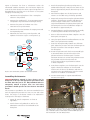
Beam Sampler 1
Detector
Beam Sampler 2
To
Experiment
From
Laser
Glan-Laser
Polarizer
Beam Dump
Spectrometer
Motorized Rotation
Stage with 1/2 Wave-Plate
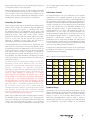
Figure 2. Block diagram of the computer controlled attenuator.
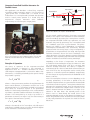
Figure 1. The computer-controlled variable attenuator. The setup consists of a
detector, a single channel power meter, a Glan-laser polarizer, a 1/2 wave-plate
mounted in a motorized rotation stage, two beam samplers, a spectrometer
and a PC
Principle of Operation
The theory of operation for the computer-controlled
variable attenuator is identical to that presented in
Application Note 26 - Variable Attenuator for Lasers
(www.newport.com/AppsNote26). It is based on Malus’s law.
The intensity, I, of linearly polarized light that passes through
the polarizer is given by
I = I o cos 2 θ
(1)
where Io is the input intensity and θ is the angle between the
beam’s initial direction of polarization and the axis of the
polarizer. Rotation of a 1/2 wave-plate mounted in a rotational
stage allows for continuous rotation of the polarization
direction of the linearly polarized light. Thus, combined with
a polarizer, it provides variable attenuation according to (1).
Rotation of the wave-plate by an angle of ϕ results in a
polarization rotation by an angle of 2 ϕ, thus the intensity at
the output of the attenuator is given by,
I = I o cos 2 2ϕ
For the manual variable attenuator, the power is measured
directly at the output of the attenuator for each wavelength
and set accordingly by rotating the 1/2 wave-plate. In contrast,
the computer-controlled closed loop attenuator sets and
maintains the power by positioning the 1/2 wave-plate based
on a feedback signal from a photo-detector. The photodetector can exhibit a strong dependence on wavelength
(www.newport.com/818Series). This chromaticity becomes
significant when the tuning range is large. Consequently, a
spectrometer is incorporated into the setup, which provides
real-time information about the laser’s wavelength, thus
taking advantage of the photo-detector’s precise wavelength
calibration. This is especially important when the laser power
needs to be held constant while scanning wavelength.
Depending on the choice of components, the attenuator
is suitable for laser wavelengths ranging from 400 nm to 1100
nm, and average powers from 1 nW up to 20 Watts (500
Watts/cm2 damage threshold). This device is capable of
attenuating light by a factor of 1000 while still maintaining an
error of less than 10%. The algorithm used to control power
operates in a closed loop with PID feedback, compensating
for slow changes in output power within the bandwidth of the
device (> 500 ms).
Prior to the wave-plate, a fraction (1%-10% depending on the
incoming polarization) of the beam is picked off by the
first beam sampler and sent to a spectrometer. The remainder
of the beam travels through the 1/2 wave-plate and Glan-laser
polarizer. The attenuated output from the polarizer passes
through the second beam sampler where a fraction of the
beam is directed towards the detector at an angle of 10º
relative to the main beam. The rejected portion of the
beam is sent to a beam dump. The overall losses of the
attenuator depend strongly on the degree of polarization, as
well as the polarization state. However, if the incoming beam
is fairly well polarized in the P-plane, the overall losses are
below 10%.
(2)
where ϕ is the azimuth of the /2 wave-plate. The full range of
attenuation is realized over 45º of rotation. The block diagram
for the attenuator is illustrated in Figure 2.
1
1