1
CHAPTER
4
HOW TO USE MINICUBE2 WITH 78K0 MICROCONTROLLER
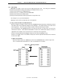
4.2.5 Clock setting
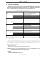
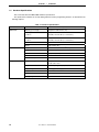
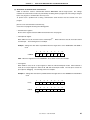
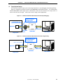
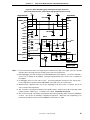
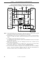
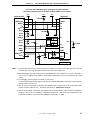
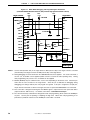
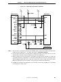
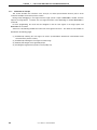
MINICUBE2 can supply a clock to be used as the high-speed system clock.
The setting of the 78K0-OCD
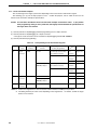
board must be performed according to the following clock supply methods (1) to (3).
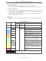
(1) Using a clock mounted on the 78K0-OCD board
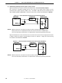
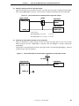
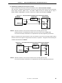
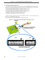
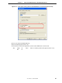
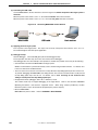
(2) Using a clock (4, 8, or 16 MHz) generated in MINICUBE2
(3) Using a clock mounted on the target system
(4) Using an internal high-speed oscillator generated in the target device only
The settings for (1) to (4) are described below.
Supplying a clock used as the subsystem clock is not supported.
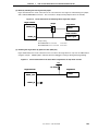
(1) Using a clock mounted on the 78K0-OCD board
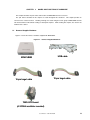
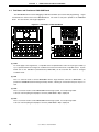
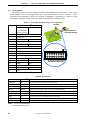
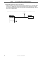
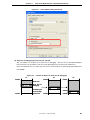
Mount an oscillator or oscillation circuit in CLK1 of the 78K0-OCD board (Clock Board is automatically selected
as the Main Clock in the Configuration dialog box of the debugger). The usable frequency is the same as that
of the target device. Refer to (a) when using the oscillator, or (b) when mounting an oscillator.
The clock mounted on the 78K0-OCD board can be used only when the X1 and X2 pins are used as the
communication interface. When OCD1A and OCD1B are used as the communication interface, the clock is
supplied from the oscillation circuit connected to the X1 and X2 pins of the target device.
However, for program download at debugger startup, the clock set by the debugger is used.
Therefore, for example, when set to 16 MHz of the System, the time required for download can be shortened
as when set to 4 MHz.
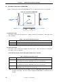
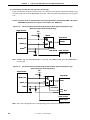
(a) When using oscillator
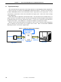
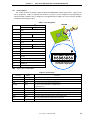
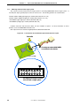
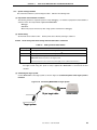
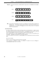
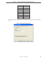
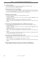
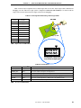
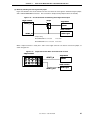
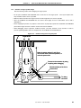
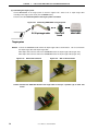
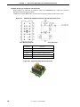
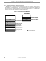
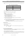
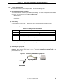
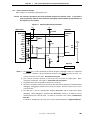
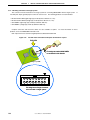
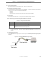
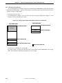
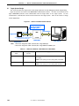
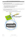
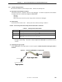
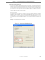
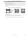
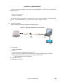
Mount the 14-pin oscillator (5 V, CMOS type) in CLK1 of the 78K0-OCD board, as shown in Figure 4-26.
TXC-1, manufactured by Tokyo Quartz Co., Ltd. is recommended as an oscillator.
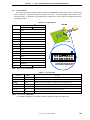
Figure 4-26.
CLK1
Mounting Oscillator
5V
14-pin type
N.C.
Clock
User’s Manual U18371EJ1V0UM
77