1
Basics of Using the YBA250
Application Note
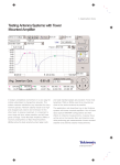
Figure 2 shows an example of a return loss measurement of a GSM
antenna that was connected directly to the test port of the YBA250.
The frequency band of this antenna is from 1850 MHz to 1990
MHz. The Blue line in Figure 2 shows the measured return loss of
the antenna. The Green line is a user-defined mask entered into the
YBA250 that shows the manufacturer’s specifications. When the
antenna meets the specification, the line is Green. The line turns
Red when it does not.
Return loss indicates how far down from the incident signal (at 0 dB),
the reflected signal is. A larger value of return loss (farther down)
indicates a smaller reflected signal, meaning a better antenna. In
other words, more power is radiated and less power is reflected.
All reflection measurement test sets introduce errors to the actual
measurement results. They are removed by a process called calibration. In general, reflection measurements are usually made as a
comparison of the device being measured to a known standard.
This standard is assumed to be perfect. The process of comparing
is called “calibrating” the measurement equipment.
Calibration
Calibration is a process that compensates for errors introduced by
the reflection measurement test set. This process uses high-precision
measurement standards whose characteristics are precisely known.
The YBA250 calculates the difference between the measurement
results from the calibration standards and the ideal results to create
correction data. This data is used to remove deterministic errors
from the measurement results.
The YBA250 uses a calibration kit that contains three precision
standards: an Open, a Short and a Load, such as the YBA250C1
(or equivalent). The accuracy of the measurements is determined
by the quality of the standards, primarily Load. A measurement may
indicate a return loss of 50 dB. This reading is meaningless, however,
if the standard load used to make the calibration was specified to
be only 40 dB.
The calibration process in the YBA250 provides a unique feature.
It is performed across its entire frequency range. Therefore, changing
the frequency parameters of a measurement does not require
re-calibration.
The YBA250 offers two types of calibration: Factory Calibration and
User Calibration. The Factory Calibration (Factory Cal) is done during
manufacturing and the results are stored in non-volatile memory
so that it can be used at any time. A User Calibration (User Cal) is
2
www.tektronix.com/wireless
Figure 2. Return Loss of a GSM antenna (Blue line).
performed before taking measurements and it also compensates
for changes in temperature and component aging to ensure the
most accurate measurement. A User Cal can be stored in the
YBA250 and it can be recalled at another time. When using a
non-precision cable to connect the YBA250 to the device under
test, we recommend performing the calibration at the end of the cable
to remove the effect of the jumper cable over the measurement results.
The Factory Cal Can be Used When:
The user does not need the best accuracy for his/her measurements
A User Cal Should be Used When:
The user wants to obtain the most accurate measurement possible
The calibration is done at the end of a jumper cable (a cable between
the YBA250 test port and the device under test)
To Perform a Quality Calibration, We Recommend:
Use of a high-precision calibration kit, such as the YBA250C1
Properly-tightened standard to ensure a good connection. A loose
connection will produce poor calibration data
Minimal cable movement when calibrating at the end of the cable
More detailed information on calibration and accurate measurements
can be found at [1] and [2] (see page 7).