1
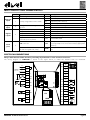
INPUT / OUTPUT / PORT CHARACTERISTICS
Number Specifications
Analogue
inputs
Digital
inputs
Digital
outputs
Serial
ports
Initials Description
1
NOT configurable, set PTC
3
Jointly configurable as PTC or NTC
2
5
PB1
Needle probe
PB2
Cold room probe
PB3
Evaporator probe (defrost)
PB4
Condenser probe
Voltage-free with closing current for DI
ground
PB5
Blast chiller door closing control microswitch
Relay R1 SPST, NO, 30 A, max. 250 V~ OUT1
Default compressor
Relay R2 SPDT 16 A max. 250 V~
OUT2
Default evaporator room fan
Relay R3 SPDT 8 A max. 250 V~
OUT3
Default condenser fan
Relay R4 SPST 8 A max. 250 V~
OUT4
Default door heating
Pressure switch
Opencollector OC for external relay
OUT5
connection, 12 Vc, 20 mA
Default NOT USED
TTL connector
TTL
Serial port to interface the parameters programming
key (Copy Card) or for connection to PC (by appropriate
interface)
KEYB
Serial port for connection between base and user interface
2
Screw connector on base side;
click-fit on keypad side, 3-way
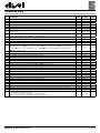
ELECTRICAL CONNECTIONS
Always switch the blast chiller off before performing any maintenance on the electrical connections.
The wiring diagram for EWBC800 is shown in the figure below, in which the default loads are illustrated.
DEFAULT NOT USED
N
N
POWER
230 Vac
L
CELL
CELL
COND
COND
COMP
1
12V
33
OC
32
2
31
3
30
4
C
5
NO2
6
NC2
7
C
8
NC3
9
NO3
10
C
11
NO1
12
13
C
14
NO4
DOOR
EWBC800 - Technical sheet for base
29
R2
28
R3
R1
R4
TTL
KEYB
GND
27
DI
26
PB5
25
PB4
24
CPB
23
PB3
22
CPB
21
PB2
20
CPB
19
PB1
18
DOOR
PRESSURE SW
COND
DEFROST
CELL
Pg. 2/4