1
Specifications may be changed without
prior notice. Printing error reserved
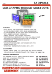
EA DIP122-5
Page 2
PINOUT
Pin Symbol Level Function
Pin
Symbol Level Function
1
VSS
L
Power supply 0V (GND)
10
D3
H/L
Display Data
2
VDD
H
Power supply +5V
11
D4
H/L
Display Data
3
VEE
-
Contrast adjustment (-4 V)
12
D5
H/L
Display Data
4
A0
H/L
Command / Data
13
D6
H/L
Display Data
5
R/W
H/L
H=Read, L=Write
14
D7
H/L
Display Data, MSB
6
E1
H
Enable left side
15
E2
H
Enable right side
7
D0
H/L
Display Data, LSB
16
RES
L
Reset
8
D1
H/L
Display Data
17
A
-
LED Backlit+ (external RV !)
9
D2
H/L
Display Data
18
C
-
LED Backlit -
CONTROLLER PT6520
Graphic modules of EA DIP122-5 series do have 2 controller PT6520 (or
compatible) built in: One for the left half of display and the other for the right
one. From 61 columns each 0..60 are used only.
PT6520 do not have any character mode, so all character has
ATTENTION
to be set by graphic. Many different fonts are optionally
available on disk with part numer EA DISKFONT1520.
A detailed description for all commands and interface timing
handling precautions!
you will find at the user manual for PT6520*).
Code
Function
A0 RD WR D7 D6 D5 D4 D3 D2 D1 D0
Display ON/OFF
0
1
0
1
0
1
0
Display start line
0
1
0
1
1
0
Display start
address (0 - 31)
Set page address
0
1
0
1
0
1
1
Set Column address
0
1
0
0
Column address (0 - 79)
B
U
S
Y
A
D
C
O
N
/
O
F
F
R
E
S
E
T
1
1
1
0
1 0/1 Turns Display on or off. 0=OFF; 1=ON;
Specifies RAM line corresponding to top
of display.
Page
Sets display RAM page.
(0-3)
Sets display RAM column address.
Read the following status:
0
1=Busy;
1=CW output;
1=Display off;
1=Being reset;
0=Ready;
0=CCW output;
0=Display on;
0=Normal;
0
0
1
Write display data
1
1
0
Write data
Writes data into display RAM.
Read display data
1
0
1
Read data
Reads data from display RAM.
Select ADC
0
1
0
1
0
1
0
0
0
0 0/1 0=CW output; 1=CCW output;
Static drive ON/OFF
0
1
0
1
0
1
0
0
1
0 0/1
Select duty
0
1
0
1
0
1
0
1
0
0 0/1 Select duty cycle. 0=1/16; 1=1/32;
Read-Modify-Write
0
1
0
1
1
1
0
0
0
0
0 Read-modify-write ON
End
0
1
0
1
1
1
0
1
1
1
0 Read-modify-write OFF
Reset
0
1
0
1
1
1
0
0
0
1
0 Software reset.
0
0
BUSY:
0 ADC:
ON/OFF:
RESET:
Read Status
Selects static driving operation.
0=Normal driving; 1=Static drive;
*) http://www.lcd-module.de/eng/pdf/zubehoer/pt6520.pdf
Instructions