1
Preparation
End of line testing must be done after all installations. Meritor
WABCO recommends using TOOLBOXTM Software to perform
A WARNING
To
this testing.
If
you do not have TOOLBOXTM Software, this
bulletin also includes instructions for testing without the
prevent serious eye injury, always wear safe eye protection
software.
when you perform vehicle maintenance or service.
The Anti -lock Braking System (ABS) is an electrical system.
When you work on the ABS, take the same precautions that
you must take with any electrical system to avoid serious
personal injury. As with any electrical system, the danger of
electrical shock or sparks exists that can ignite flammable
Installation
I.
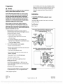
Install the ECU /dual modulator valve
assembly.
substances. You must always disconnect the battery ground
The assembly may be mounted on the air tank or on the cross
cable before working on the electrical system.
member of the vehicle.
Park the vehicle on a level surface. Block the wheels to
prevent the vehicle from moving. Support the vehicle with
safety stands. Do not work under a vehicle supported only by
jacks. Jacks can slip and fall over. Serious personal injury and
damage to components can result.
Tank -Mounted
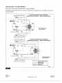
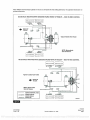
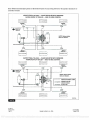
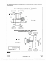
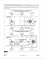
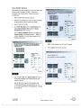
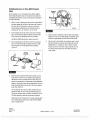
Refer to Figure 2.
ECU /DUAL MODULATOR VALVE MOUNTED WITH
1.
SENSORS FACING FRONT OFTRAILER
(TANK- MOUNTED)
Before beginning the installation procedure, inspect the
modulator valve assembly for damage that may have
occurred during shipping or storage.
ECU /dual
CURBSIDE
Look for crushed or bent connectors.
VE2
Verify that the retainer clips have not been bent or
CURBSIDE
otherwise damaged.
YE1
Do not install a damaged ECU /dual modulator valve
assembly. Notify your supervisor, or contact Meritor WABCO
if there is any apparent damage.
2.
/
ROADSIDE
BU1
ROADSIDE
BU2
Have the following installation material available.
* ECU /dual modulator valve assembly
* ABS relay valve and relay valve extension cable with bayonet
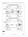
ECU /DUAL MODULATOR VALVE MOUNTED WITH
SENSORS FACING REAR OFTRAILER
connector (3M systems)
* Power cable or power /diagnostic cable
* Sensor extension cables (two pieces for 2S systems, four
pieces for 4S systems)
CURBSIDE
BU2
* Sensors (two or four) for non -ABS prepped axles
CURBSIDE
BU1
* ABS Indicator Label (TP- 95172)
U!!
5/8 -inch O.D. nylon tubing for supply (frame mount)
Pipe plug (3/4 -inch NPTF)
Schedule 80 hex pipe nipple (3/4 -inch NPTF) for air tank
mounts or two Grade 8 bolts (3/8 -inch) and prevailing torque
PLUG UNUSED
PORT
nuts for frame mounts
SAE -standard, DOT- approved thread sealant
To
ROADSIDE
R
YE1
ROADSIDE
VE2
Exhaust port
must face DOWN.
4003548a
ensure correct lamp operation, use an incandescent -type
Figure 2
DOT- approved lamp, or an LED with integral load resistor.
* Meritor WABCO components
TP -20214
Revised 10 -05
Page 2
i
(16579/22882)
Copyright ArvinMeritor, Inc., 2005
Printed
in
USA
PDF compression, OCR, web optimization using a watermarked evaluation copy of CVISION PDFCompressor