1
* Continued from previous page.
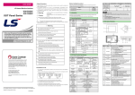
키
Function description
- The function assigned to ◀ key is executed.
- If there is no defined function, go to the previous screen defined in the current
screen.
- When changing the value of the digit tag, move the current cursor position to
the left.
◀
7) Buzzer, backlight set
(1)
(2)
(3)
- The function assigned to ▶ key is executed.
- If there is no definition, go to the next screen defined in the current screen.
- When changing the value of the digit tag, move the current cursor position to
the right.
▶
SET
- Enter the value-changing mode.
ENT
- In value-changing mode, write the set value.
- Enter the setting menu.
- Execute the selected item in menu.
* G4M-CPUC in LS PLC does not support 5V supply.
3) RS–422/485 communication interface
With the RS-422/485 communication interface of the XGT Panel, data
communication like 1:1, 1:N multi-drop, N:M multi-master with PLC,
inverter and various kinds of control units is possible. In this case,
communication cable must be wired properly.
Cable wiring for communication with LS PLC is as follow, and for more
details, refer to the XGT Panel user’s manual.
(1)
3) N:M multi-master communication system configuration
The XGT Panel supports N:M multi-master and multi-slave communication. The XGT Panels which are set as a master communicate with slaves
in turn using the token. In this case, every XGT Panel set as a master
must have same communication setting data except HMI station number.
The total settable station number is 32.(station 0 – 31)
RS-422 communication wiring
If the key is valid the buzzer beeps 1 time, if not, 3 times.
If you select 5 of 6)-(1) menu, the volume level of the buzzer can be
adjusted.
If you select 6 of 6)-(1) menu, backlight can be ON/OFF.
In case that backlight option is selected, if no key is inputted during
setting time, backlight will be off automatically. In this case,
whichever key is pressed, the function assigned to the key is not
executed but backlight is just on.
8) Changing screen
(1)
(2)
(3)
(4)
When the power is supplied to a XGT Panel, the defined first screen
will be displayed. If it doesn’t exist, the first defined screen will be
displayed.
In monitor mode, the defined screen list will be displayed if ESC key
is pressed. Using ▲, ▼, ENT key, it is possible to change the screen.
In monitor mode, pressing ◀, ▶ key, the screen will move to the
defined previous, next screen for each. If the screen doesn’t exist, no
move will happen.
In case that screen saver option is set, if no key is inputted during
setting time, the screen will be move to the defined screen. At this
time, whatever key is inputted, the screen won’t move and the
function assigned to the key will be executed. If the screen doesn’t
exist, no move will happen.
3) Writing data
9) Continuous keystroke
(1)
The tags which are possible to write the data are digit tag and button
tag. But in case that password is set, password must be unlocked
before writing the data.
In monitor mode, pressing the SET key leads to value-changing
mode. If there’s no tag to be written to, it will be invalid.
The cursor will be located on the nearest tag to the left top of the
screen.
If the SET key is pressed again, the cursor moves to the next writing
enabled tag.
In case of digit tag, after changing the value of the tag with arrow
keys, execute writing the value with ENT key. In case of button tag,
when the cursor is located on the tag, execute the order defined on
the tag with ENT key.
(2)
(3)
(4)
(5)
When pressing a key, if the key is held down for more than 1 second, the
function assigned to the key will be executed repeatedly.
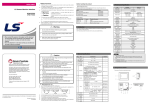
8. Dimension(mm)
1) External dimension
LS
4) Alarm
(2)
(1)
RS-485 communication wiring
(2)
In alarm state, the alarm message is displayed at the bottom of the
screen flickering. If the buzzer option is set, it will beep. At this time,
only ESC and ALM key are valid. In XP10BKB/DC type, two time
data will be saved. One data is the time when the alarm happened
and the other data is the time when it was cleared.
In monitor mode, the following messages will be displayed if ALM key
is pressed.
1. ALL ALARM LOG LIST
2. DEFINED ALARM LIST
120Ω, 1/2W Terminating Resistor is Recommended
If you select 1, the recent alarm messages will be displayed up to 100 items
in order
If you select 2, the recent Defined Alarm list will be displayed up to 10 items
in order.
7. Operation
1) Introduction
This chapter explains the operation of the XGT Panel. For more details
refer to the user’s manual.
This chapter describes information about the communication system configuration.
1) 1:1 communication system configuration
The XGT Panel has two independent channels which are RS-232C and
RS-422/485. It is possible to configure flexible 1:1 communication
system with them.
The following is an example configured with a XGT Panel, a PLC and an
inverter.
2) 1:N communication system configuration
This part explains 1:N multi-drop configuration with RS-422/485 channel
of the XGT Panel. In this case, the XGT Panel becomes a master and
other units become slaves.
The total settable station number is 32.(station 0 – 31)
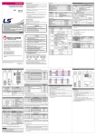
5) Password
(1)
2) Key
Key
Function description
F1
- The function assigned to F1 key is executed.
- For details about the function, refer to the user’s manual
F2
- The function assigned to F2 key is executed.
F3
- The function assigned to F3 key is executed.
F4
- The function assigned to F4 key is executed.
ESC
- Display the names of screen defined.
- Cancel the change of the value, or go back in case of menu.
- In case of alarm, clear the alarm message displayed in the screen.
ALM
- Display alarm history.
▲
- The function assigned to ▲ key is executed.
- When changing the value of the digit tag, increase the number of the current
cursor position by 1.
- Move up the cursor in menu.
▼
- The function assigned to ▼ key is executed.
- When changing the value of the digit tag, decrease the number of the current
cursor position by 1.
- Move down the cursor in menu.
(2)
2) Cutting dimension
In case that password is set to the XGT Panel, it is impossible to
write data to the writing enabled tag and to execute the function key
set password at. In this case, it doesn’t operate normally until the
password is released.
In monitor mode, the following menu will be displayed if ENT key is
pressed.
87±0.5
6. Communication System Configuration
1. PASSWORD UNLOCK
2. PASSWORD LOCK
3. PASSWORD CHANGE
If you select 1, the password become unlocked if you input correct password.
If there is no password, the following message will be displayed.
141±0.5
PASSWORD NO EXIST!
In state that password is unlocked, the operations which is set password to is
executable.
This is valid until the password is locked.
If you select 2, the password is locked.
If you select 3, the password is able to be changed.
The password is less than 10 digits.
* If the password is set to 0, it is cleared.
Caution
►
Do not forget the password
If the password is forgotten, you may not be able to use the major functions
of the product.
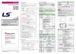
9. Warranty
1. Warranty period
LSIS provides an 18-month-warranty from the date of the production.
2. Warranty conditions
For troubles within the warranty period, LSIS will replace the entire HMI or repair the
troubled parts free of charge except the following cases.
(1) The troubles caused by improper condition, environment or treatment except the
instructions of LSIS.
(2) The troubles caused by external devices.
(3) The troubles caused by remodeling or repairing based on the user’s own
6) Date / Time set(XP10BKB/DC type only)
* Continued on next page.
(1)
When the cursor is on 3 of 5)-(2) menu, pressing ▼ key leads to the
following menu.
4. DATE / TIME SET
5. BUZZER VOLUME SET
6. BACKLIGHT SET
If you select 4, current date and time will be displayed.
They can be changed with SET key.
The date and the day of the week must correspond.
discretion.
(4) The troubles caused by improper usage of the product.
(5) The troubles caused by the reason which exceeded the expectation
from science and technology level when LSIS manufactured the product.
(6) The troubles caused by natural disaster.
3. This warranty is limited to the HMI itself only. It is not valid for the whole system which the
HMI is attached to.