1
CHAPTER I
PRESENTATION
Aimpoint’s Reflex Sights are rugged precision electronic optical red dot
sights developed for civilian, military and law enforcement applications.
Aimpoint sights are designed for the ”two eyes open” method of sighting,
which greatly enhances situational awareness and target acquisition speed.
Thanks to the parallax-free design, the dot follows the movement of the
user’s eye while remaining fixed on the target, eliminating any need for
centering. Further, the sight allows for unlimited eye-relief. The
Patrol Rifle Optic is compatible with 1st , 2nd and 3rd generation night
vision devices.
The Patrol Rifle Optic sight is using Advanced Circuit Efficiency Technology
(ACET), which combines Aimpoint’s superior accuracy and ease of use with
significantly lower power usage.
If you have further questions, please contact your local dealer.
SPECIFICATION
Material – housing: Extruded, high strength aluminum, anodized
Material – lens covers: Thermoplastic elastomer, black, non-glare
Surface finish: Hard Anodized, Dark Graphite Grey, matte
Rubber cover: Black or Dark Earth Brown
Optical magnification: 1X
Eye relief: Unlimited, no centering required
Optical coating: Anti Reflex coating, all surfaces
Multi-layer coating for reflection
Band Pass coating for NVD compatibility
Dot size: 2 MOA
Switch, dot brightness: 10 positions: 4 NVD, 6 daylight of
which 1 Extra Bright
Battery: One 3 Volt Lithium battery type
2L76 or DL1/3N
Battery life (hours): 50,000 h on setting 7 out of 10,
(ACET Diode)
Typically 500,000 h at NVD setting
Length (incl. lens covers): 130 mm (5.1”)
Width: 55 mm (2.2”)
Height: 55 mm (2.2”)
Weight (sight only): 220 grams (7.8 oz)
Weight (with integrated
mount) 330 grams (11.6 oz) including mount and
spacer
Adjustment: Range ±2 m at 100 meters, in windage and
elevation 1 click = 10 mm at 80 meters =
13 mm at 100 meters = 1/2” at 100 yards.
Mounting: One wide ring, 30 mm diam, or Aimpoint QR
Ring
Max temperature range: -45 ºC to +70 ºC (-50 ºF to +160 ºF)
Water resistance: Submersible to 45 m (150 ft) water depth
MOA: Minute Of Angle 1MOA = 30 mm at 100 meters = 1” at 100 yards
NVD: Night Vision Device
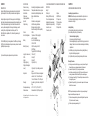
1.3 LOCATION AND DESCRIPTION OF MAJOR COMPONENTS AND
FUNCTIONS
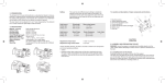
See fig. 1
1. Battery Lid
8. Spacer
2. Battery (DL1/3N or similar)
9. QRP2 Mount
3. Cover for adjustment screw
10. Torque knob
4. Adjustment Screw (windage)
11. Mounting Screw
5. Adjustment Screw (elevation)
12. Ring Mount
6. Lens Cover, rear
13. Rotary Switch
7. Lens Cover, front
CHAPTER II
OPERATION UNDER NORMAL CONDITIONS
Assembly and preparation for use
WARNING: Insure the weapon is unloaded and the safety selector is in
the ”safe” position before attempting to install, remove or perform
maintenance on the sight.
Installing Battery
a) Remove battery cap by turning it counter clockwise.
b) Insert battery with positive (+) end toward cap.
Caution while replacing battery
(not necessary when the sight is unused)
Before installing battery cap, inspect that the O-ring is present and not
damaged. Failure to do so could result in water leakage into the battery
compartment.
c) Install battery cap by turning clockwise until snug. Hand tighten only.
Using tools could damage equipment.
d) Verify that red dot is present by turning the rotary switch clockwise.
Mounting Procedure
a) Select a groove on the rail that will give you a correct position of the sight. Ensure that the groove is undamaged and clear of dirt and sand.
b) Loosen the Torque Knob (10) by turning it counterclockwise.
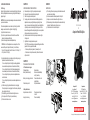
c) Install the mount and sight on the rail (fig. 1). Make sure that the mount is
correctly positioned and that the Recoil Stop is in the selected groove.
d) Push the mount forward (fig. 2). The Recoil Stop shall be in contact with the
front edge of the groove.
e) Tighten the Torque Knob (fig. 3) clockwise until it snaps twice. This ensures that the Mount is secured.
NOTE: Grasp the checkered portion of the knob only to prevent pinching of
fingers when the shaft opens and snaps shut.
f) Test shoot the weapon with the sight mounted. Retighten the Torque Knob (10) after a few rounds, if necessary.
g) Perform complete zeroing according to 2.2.1.