1
1.3. SIMULATION ENVIRONMENTS
7
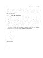
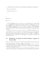
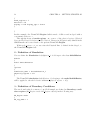
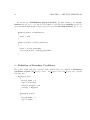
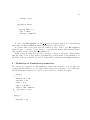
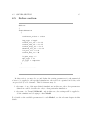
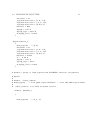
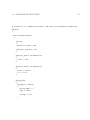
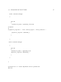
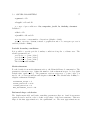
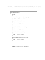
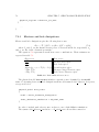
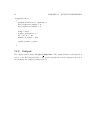
As before, it is possible group more boundary regions in a single BC Region, with
the keyword BC reg numb
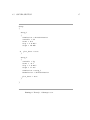
BC_Regions
{
BC_Region cathode
{
BC_reg_numb = (contact1,
contact2)
......................
....................
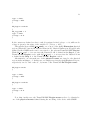
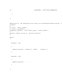
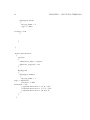
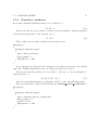
Again, in this second case, cathode is a label chosen by user, while contact1 and
contact2 are labels previously defined inside GMSH.
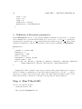
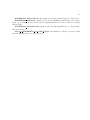
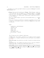
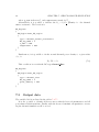
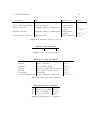
In 2D case, a set of Physical Surface will be defined to be used as mesh regions,
while Physical Line is used for boundary regions.
Finally, in 3D case, Physical Volume is used to define mesh regions, while Physical Surface is used to define boundary regions.
1.3
Simulation environments
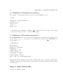
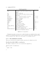
TIBERCAD allows to compute different physical models in different parts of a device or
nanostructure by coupling in a general way different simulation environments. A simulation environment is composed by all the physical regions to which a particular model is
assigned. A simulation environment is therefore defined by the mesh elements belonging
to its physical regions and by the simulation model which has been associated to these
regions. This association is made possible by the definition of TIBERCAD Regions and
Clusters. Different simulation environments can have physical regions in common. In
this way, each simulation is run on a subset of the device and can be possibly coupled
(even self-consistently) with a simulation run on a different subset of the device corresponding to a simulation environment with a non-void intersection with the first one.
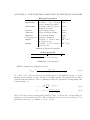
The coupling of the two simulations is performed by means of appropriate Boundary
Conditions (e.g. Current Density, Voltage, ...). In principle, the two simulation environments can refer to two simulations at different scale, e.g. atomistic tight-binding and
macroscopic drift-diffusion. This allows an effective multi-scale simulation of the device
to be studied.