1
14
CHAPTER 3. GETTING STARTED 2D
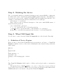
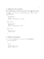
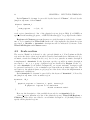
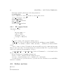
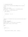
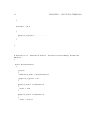
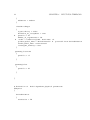
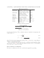
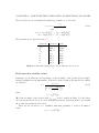
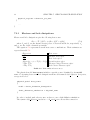
xd = Lg_2 + d;
xd2 = Lg_2 + d / 2;
xmax = xd + Ls - d;
These other convenient variables are used to parametrize the most relevant geometrical
features, such as channel length, oxide thickness, and so on.
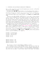
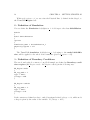
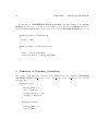
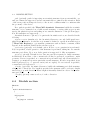
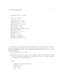
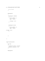
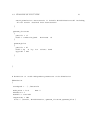
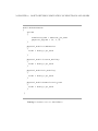
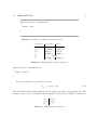
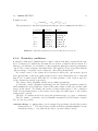
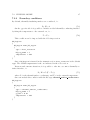
Point(1) = {0, -h, 0, lsub};
Point(2) = {0, 0, 0, lc};
Point(3) = {xmax,-h,0.0,lsub};
Point(4) = {-xmax,-h,0.0,lsub};
Point(5) = {xmax,0,0.0,lh};
Point(6) = {-xmax,0,0.0,lh};
..........................
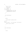
Line(1) = {4,1};
Line(2) = {3,13};
Line(6) = {4,14};
Line(7) = {10,9};
Line(8) = {12,2};
Line(9) = {8,7};
Line(10) = {11,8};
Line(11) = {9,12};
Line(13) = {7,6};
..........................
• Geometrical Points and Lines are defined to design the device structure; the
fourth parameter in Point assignement is the characteristic length associated to
that point: this is an essential feature to control the mesh density and refine it
where necessary (usually n the channel region).
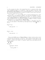
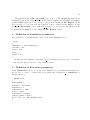
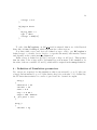
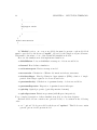
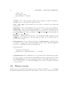
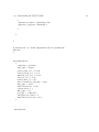
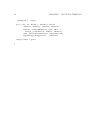
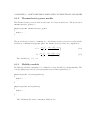
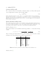
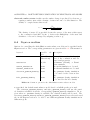
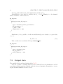
Line Loop(40) = {28,2,-34,33,8,29,-31,-30,-6,1};
Plane Surface(41) = {40};
..........................
• Definition of a surface: first a line loop is composed, listing all the lines constituting the boundary of the surface; then this line loop is assigned to a Plane
Surface object (this procedure can be alternatively performed throgh the graphical
interface).