1
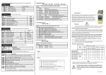
CONNECTION DIAGRAMS
TERMINAL N.
PE L1 L2
POWER AND CONTROL TERMINALS
TOPSINGLE PHASE
FEED
SINGLE PHASE FEED
Single phase 50 Hz/60 Hz +/- 5%
220 V (-15%) - 240 V (+10%)
G
PR
RRM
WE UN
PO
R
ALA
FRONTCOPY KEY
O
O
O
. . . .
0000
Display
M
Menù
E
Reset
Enter
V
Function Led's
Yellow
ON= Inverter power
Flashing=Programming mode
Green
RUN command enabled and active
Red
Inverter allarm state
V
1 2 3 4 5 6 7 8 9 10 11
JP 5
15 16 17
Control
terminal
Common
REL-CM 1 Relè
230 Vac 0.2 A
REL-NO 2 [I-100 ] Normally open
30Vdc
1A
REL-NC 3 (1)Alarm Normally closed
4 +15V Potential
+15 V
15V +/- 5% 300mA
5 Digital input 1
IN1
I-000 (1)RUN
6 Digital input 2
7mA @ 15V
IN2
I-001 (3)EF
PNP logic
7 Digital input 3
IN3
I-002 (2)REV
8 Digital input 4
IN4
I-003 (7)SFreq.
Analog input
9 0 V potential for analog input
GND
10 Programmable analog input 1 I-200 =1 Voltage Ri=20kOhm
ANIN1
Current Ri=500Ohm
11 +10V Potential
+10 V
JP5
Converts Voltage input (J5 not fitted)
to
Current input (J5 fitted)
JP7
GND-U
FB +
FB -
Limits potential of earth terminals
15 Reference ground
16 Serial line + (optional)
17 Serial line + (optional)
RS 485
PARAMETRS MENU
U V W PE
d -xxx
S-xxx
III-xxx
fff -xxx
P-xxx
A-xxx
C-xxx
THREE
PHASE
MOTOR
FIT JP5 FOR USE WITH CURRENT ANALOG INPUT.
Read only parameters display menu
Basic inverter parameters setting menu
Programmable inputs and outputs setting menu
References and ramps setting menu
Inverter functioning parameters setting menu
PID block parameters setting menu
Function execution menu (for functions like parameter saving and
inverter auto-calibration)
NOTE ! Menù S, START-UP, groups together the parameters and functions
necessary for quick and easy start-up of the inverter and the controlled motor. All the
parameters in the STARTUP menu are duplicated in other menus. Changes to any
parameter in the STARTUP menu automatically change the same parameter in the
other menu.
Control terminal
1
2
3
4
5
6
7
8
IN1
IN2
IN3
IN4
9
AN IN 1
+ 10V
GND
Freq.Sel.
REV
Ext F
RUN
CM NO NC
EDITING PARAMETERS
Potentiometer
+ 15V
Programmable relay
OUTPUT [ I100 ]
OUT 1
10 11
JP5
15 16 17
GND
RS 485 [if optional
card fitted]
FB+ FB-
JP5 fitted: the ANALOG
INPUT is a current input
[I200].
1 0-10V or 0-20 mA
2 4-20 mA
JP7 Limits ground
regulation potential.
For the equipment to operate in safe conditions it must be
installed and started up by suitably qualified personnel in compliance with all relevant safety standards applicable to high current
and high voltage electrical equipment.
MAX
Use the keyboard to access the parameters. Press M to display the desired
menu. Use the arrow , up and arrow down keys to select the code of the
parameter whose value you wish to display, then press E to display that value.
8-10-11 Notused in standard version
15-16-17 Serial output (if provided)
THREE PHASE
MOTOR
FUNCTION
JP 7
Notfitted IN AN [V]
Fitted IN AN [A]
BOTTON
STARTUP
CONTROL CONNECTIONS
Let us assume that we have powered the inverter on and that we wish to change the
acceleration ramp value F-201 from 5 (factory default value) to 10 seconds.
On power-up the display reads out 000. Press M repeatedly to display menu F (F000 ); Use the arrow , up and arrow down keys to select code 201(F-201). Press
E. The value of the parameter f-201 (AccTime1) is displayed. If the PRG LED is
steadily lit, the parameter value can be changed. Press the arrow up key until the
display reads out 10. Press E to enter the new value.
This changes the active value for the acceleration ramp but does not save
it (the yellow LED flashes).
Press M to display C. Use the arrow , up and arrow down keys to select the code
C-000 ,. Press E to confirm your choice. The display reads out off . If the PRG LED
is steadily lit, the value can be saved. Use the arrow up key to enable the function.
The display reads out Do. Press E to confirm. The display reads out done (value
saved).
Parameter settings
Check the following parameters before starting up the inverter:
S - START-UP menu Basic drive start-up menu.
PARA
METER
S-000
S-001
S-100
S-101
S-200
S-201
S-202
S-203
S-300
S-301
S-400
S-900
S-901
[*]
[**]
ALIAS
Description
Mains voltage (V)
Mains frequency (Hz)
Maximum output voltage (V)
Base frequency (Hz)
START & STOP command source (1= terminals)[*]
Maximum analog reference frequency
Reference channel source [**]
Digital reference frequency
Ramp-up time
Ramp-down time
Manual boost
Stator resistance measure command
Parameter save command
DEFAULT
p-020
p-021
p-061
p-062
p-000
f-020
f-050
f-100
f-201
f-202
p-120
110/230
50
110/230
50
1
50
3
0
5 sec
5 sec
3
C-100
off
off
C-000
S-200 =1 control from terminals
S-200 =2,3,4 reserved for serial line control
S-202 Source of speed reference
S-202 =3 reference from digital frequency = S-203
S-202 =1 reference from analog input [Vedi I-200 ]
Starting
1) Connect a potentiometer (minimum resistance 4.7 kOhm) for the speed reference
(terminals 9, 10, 11).
2) Connect two contacts for the Run and Reverse commands closing on +15V
(terminals 4 and 5 for Run, 4 and 7 for Reverse).
3) Close the Run contacts to start the motor. The motor starts and follows the set ramp
to the set frequency (default F-201=5 = 5 seconds).
Stopping
The motor can be stopped in two ways:
1.
By de-activating the Run command. The motor stops with the factory default
deceleration ramp (F.202 = 5 seconds from max. frequency to 0 Hz).
2.
Setting the speed reference potentiometer to 0 for manual control over motor
stopping.
Warning! If the motor is stopped in this way it remains live even when not rotating.
If the motor fails to run
If the motor fails to start after the Run command, first make sure that the connections
specified above have been made correctly, then check that the factory default
parameters are suitable for the specifications of the motor.
USING THE PROGRAMMING KEY
Transferring parameters from the inverter to the key
· Insert the key into the socket above the display
· Use the keyboard to select the C-041 parameter, press arrow up, then Enter.
The display reads out " done " for 2 seconds to confirm data transfer.
Transferring parameters from the key to the inverter
· Insert the key into the socket above the display
· Use the keyboard to select the C-040, parameter, press
arrow up, then Enter.
The display reads out " done " for 2 seconds to confirm data transfer.