1
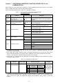
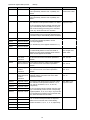
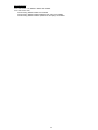
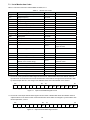
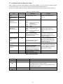
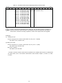
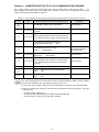
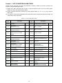
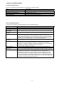
(2) Remote inputs (Inverter Master) Device No. RX0 Signal name Running forward Description OFF: Except running in forward direction (Stopped or Rotating in reverse direction) ON: RX1 Running reverse Remarks -- Rotating in forward direction OFF: Except running in reverse direction (Stopped or Rotating in forward direction ON: -- Rotating in reverse direction RX2 Terminal Y1 function Terminal status assigned by inverter's *1 function code E20 Factory default: RUN RX3 Terminal Y2 function Terminal status assigned by inverter's *1 function code E21 Factory default: OL RX4 Not used. -- -- RX5 Not used. -- -- RX6 Not used. -- -- RX7 Terminal 30A/B/C function Terminal command assigned by inverter's function code E27 *1 RXC Monitoring This signal is turned ON when turning the "Monitor command" (RYC) ON has caused the inverter to store monitored values into remote registers RWr0, 1, 4 to 7. Factory default: ALML Turning the "Monitor command" (RYC) OFF turns this signal OFF. RXD Frequency setting completed This signal is turned ON when turning the "Frequency command" (RYD) ON has written the reference frequency into the inverter. Turning the "Frequency command" (RYD) OFF turns this signal OFF. RXE Not used. RXF Command code execution completed -This signal is turned ON when turning the "Command code execution request" (RYF) ON has completed the execution of processing corresponding to command codes (specified in RWw2, 10, 12, 14, 16, and 18). Turning the "Command execution request" (RYF) OFF turns this signal OFF. RX1A Alarm state flag This signal is turned ON when the inverter has tripped. RX1B Remote station ready This signal is turned ON when powering on the inverter or resetting the hardware has readied the inverter. (This signal is used for interlocking with reading or writing from/to the master unit.) This signal is turned OFF concurrently when the "Alarm state flag" (RX1A) is turned ON if the inverter trips. *1 For details about inverter's function codes E20, E21 and E27, refer to the FRENIC-Multi Instruction Manual (INR-SI47-1204-E), Chapter 5 "FUNCTION CODES." 21