1
708
Fall Joint Computer Conference, 1969
----------------------------------------,--tailed design process. If l1ot, the designer may
al ter his architecture.
To satisfy the above needs, Digital Control Design
Language (DCDL) has been implemented as part- of
design automation research being conducted at the
University of California at Los Angeles. 2- 6 A. compiler
for DCDL has been implemented for the SSD SIGMA
7 using a META 5 compiler writing systcm. 6 ,7 The
DCDL compiler is currently also being implemented
for the IBM/360.
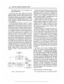
The DCDL system illustrated in Figure 1 contains
two compiler processors written in META 5, a pseudo
machine (which is the subject oithis paper) written in
FORTRAN IV and the machine language, and twO"
control implementation modules written in FORTRAN
IV. T~e input processor is a DC:r;>L syntactic analyzer;
(~) thIS program translates the digital system descriptIOn (example in Part IV) into an interpretive code
used by the pseudo-machine for simulation of the
described hardware. The second META 5 processor
(2) produces a numerical code which is then transformed
into a binary control program and a fabrication description of a control subsystem for the computer system
being designed. The implementation specificatio~s for
the wiring of the control matrices are produced by the
two FORTRAN IV programs (3,4). Control modules
imp~ied by microprograms have their wiring lists automatICally generated by the Control Matrix Processors
in DCDS. The hardware construction of the controi
processor is then effected by using a set of one or more
similar building blocks (Control Matrix Building
Blocks), according to wiring specifications given by
DCDS.
The software module described in Part III is a pseudo
machine {5) in charge of executing simulation runs.
The pseudo machine is composed of a combination of
FORTRAN IV and machine language subroutines. The
simulation runs are designed to check test cases in
order to ass~ss the validity of a described design as well
as to calculate its estima.ted execution time.
DCDS is designed to analyze asynchronous as well
as clocked systems, with the former posing a. spedal
problem: dynamic reevaluation of variables. Any time
a logical variable is changed, the system must, as a
consequence of this change, reevaluate any other
variable which is a function of the changed variable.
This process must continue until no further "consequential changes" occur.
DCDS's capability to dynamically reevalua,te vari_abIes allows the designer to describe his system using
-the same logical equations and timing relations which
he uses to implement it. Programming in a form (see
Part IV) which is highly related to the actual hardw:are
provides for a system directly used by the designer
eliminating the programmer as a "middle-man". This
direct correspondence also makes the DCDL progr:am
an up-to-date documentation of the system designed.
The syntax analyzer accepts a description which images
the hardware and translates this description into
simulation code. Thus the designer is freed from the
tedious job of programming the structure-of the model
required-a process sometimes more time-consuming
than building a hardware prototype and testing it on
the bench.
'rhe Digital Control Design Lang~ge (DCDL)
is built as a ~luster of three ntain sublanguages: a
language intended for expressing ~~olean €:guations
and time relations; a microprogramming language;
and an algorithmic language. DCDL uses FORTRAN
as the algorithmic sublanguage. The user may choose
anyone of the three sublanguages to describe any of
the parts or module"s in the describ~d design. The logical
aI).d micl'oprogrammi'nlg sublangu~g~s use the s~me
declarations and access the same variables by their
names. The execution statements of sublanguages a.nd
their syntactic formats differ and one cannot combine
statements of different sublangu,ages. Thus DCDS
~rovides' the user with a powedul means of expression,
since he can select the most convenient and expressive
form from among the three s'ublanguages to describe
a hardware module.
Entities and attributes in simulation systems
Figure I-DCDS system flow chart.
For our observations herein, we consider the simula-
From the collection of the Computer History Museum (www.computerhistory.org)