1
ITEM
NO.
DESCRIPTION AND SPECIFICATION
DELIVERED WEEKS/MONTH
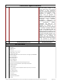
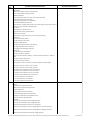
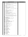
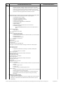
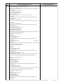
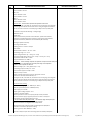
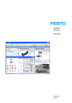
• Can be use for controlling, monitoring, analysis, commissioning and testing of
the following:
1. Electro-Pneumatics
2. Electro-Hydraulics
3. Process control (optimization for 2 point controller, P, PI, and PID)
4. Servo/stepper motor
5. Mechatronics stations (different modules)
6. Different PLC’s (Programmable logic controller)
7. Sensors
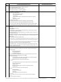
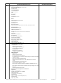
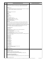
3. WBT (web-based Training) Electropneumatics (1)
4. Textbook; Basic Principles of pneumatics and Electropneumatics (1)
5. DVD Electropneumatics (1)
6. Easy port USB for and interface for measuring,
open-loop control, closed loop control (Simulation between hardware and software
without using PLC) (1)
74
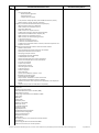
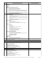
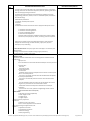
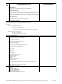
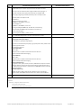
Basic Electro-hydraulic Trainer with Aluminum Profile, power pack and Accesories
Components:
1. Pressure
relief valve - The valve limits the pressure at port P relative to the pressure at T to the set value.
• Adjustment: manual
• Includes non-return valve
• Operating pressure 6 MPa (60 bar)
• Maximum permissible pressure 12 MPa (120 bar)
• Low-leakage, self-sealing coupling nipples
• Quick action mounting system Quick-Fix
2. 2-way flow control valve - The valve ensures a constant volumetric flow rate in the flow
direction from A to B, regardless of the load pressure on B. The oil can flow from B to A via the
non-return valve which opens.
• Actuation: manual
• Differential pressure of the pressure balance 0.55 MPa (5.5 bar)
• Operating pressure 6 MPa (60 bar)
• Maximum permissible pressure 12 MPa (120 bar)
• Low-leakage, self-sealing coupling nipples
• Quick action mounting system Quick-Fix
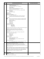
3. One-way flow control valve - The valve is used to influence the volumetric flow rate
through an adjustable throttle point, in one direction. In the opposite direction, the throttle is
bypassed using the non-return valve.
• Actuation: manual
• Integrated non-return valve
• Operating pressure 6 MPa (60 bar)
• Maximum permissible pressure 12 MPa (120 bar)
• Low-leakage, self-sealing coupling nipples/quick coupling socket
4. • Non-return valve - The valve is closed by a locking cone which is pressed against the seat
by a spring. When the opening pressure on the seat side is exceeded, the valve opens and fluid
can flow through it. When the pressure on the spring side is greater, the valve remains closed.
• Actuation: hydraulic
• Tube length 1000 mm
• Operating pressure 6 MPa (60 bar)
• Maximum permissible pressure 12 MPa (120 bar)
• Low-leakage, self-sealing quick coupling sockets
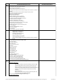
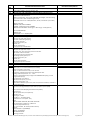
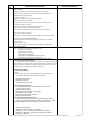
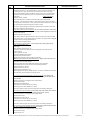
• 4/2-way solenoid valve, spring return
• Actuation: switching solenoid
• Operating pressure 6 MPa (60 bar)
• Maximum permissible pressure 12 MPa (120 bar)
• Valve port pattern, hydraulic ISO/DIN 4401 size 02
• Low-leakage, self-sealing coupling nipples
• 24 V DC power
Technical Specifications-Re-Bidding of Lots 3, 8 and 11 Various Laboratories of the College of Industrial and Information Technology (CIIT)
Page 55 of 66