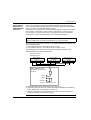
1
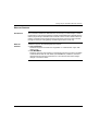
System Bits and Words
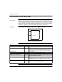
System Bits (%S)
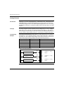
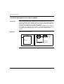
Introduction
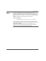
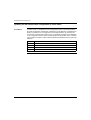
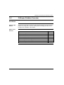
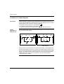
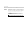
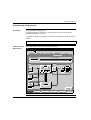
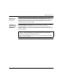
The following section provides detailed information about the function of system bits
and how they are controlled.
Detailed
Description
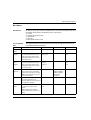
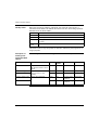
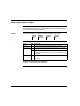
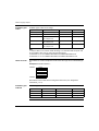
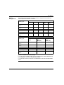
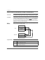
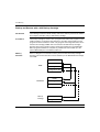
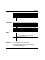
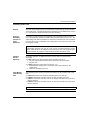
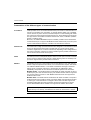
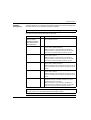
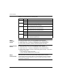
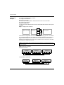
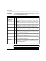
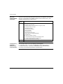
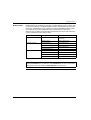
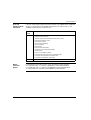
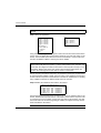
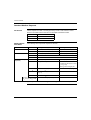
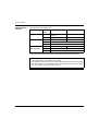
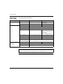
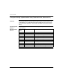
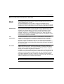
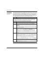
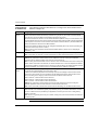
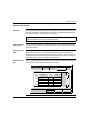
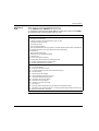
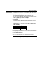
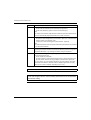
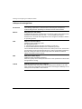
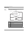
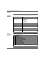
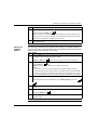
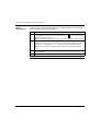
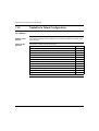
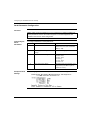
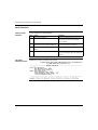
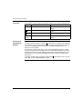
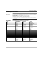
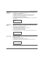
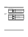
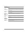
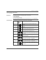
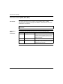
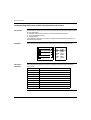
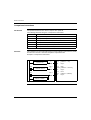
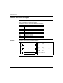
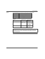
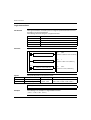
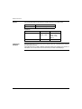
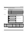
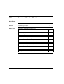
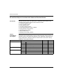
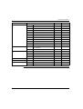
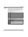
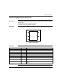
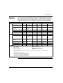
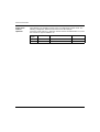
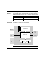
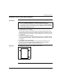
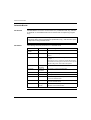
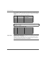
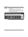
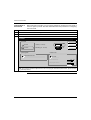
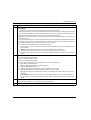
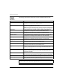
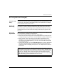
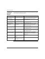
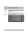
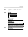
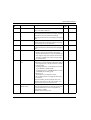
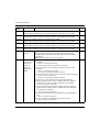
The following table provides an overview of the system bits and how they are
controlled:
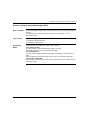
System
Bit
Function
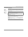
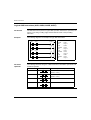
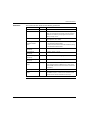
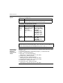
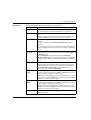
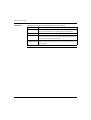
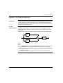
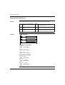
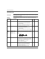
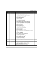
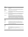
%S0
Cold Start
Description
Normally set to 0, it is set to 1 by:
Init
state
Control
0
S or U->S
0
S or U->S
-
S
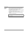
z A power return with loss of data (battery fault),
z The user program or Animation Table Editor,
z Operations Display.
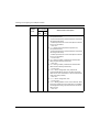
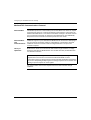
This bit is set to 1 during the first complete scan. It is
reset to 0 by the system before the next scan.
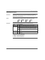
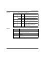
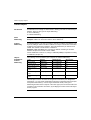
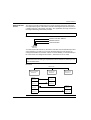
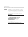
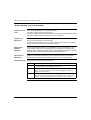
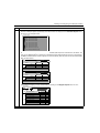
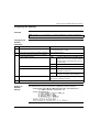
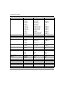
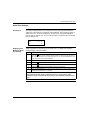
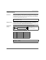
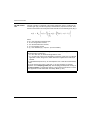
%S1
Warm Start
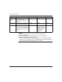
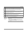
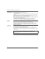
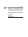
Normally set to 0, it is set to 1 by:
z A power return with data backup,
z The user program or Animation Table Editor,
z Operations Display.
It is reset to 0 by the system at the end of the complete
scan.
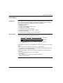
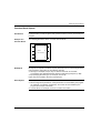
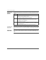
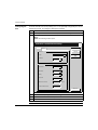
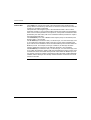
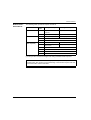
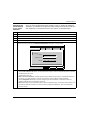
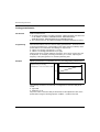
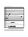
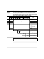
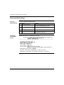
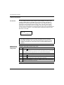
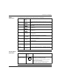
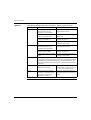
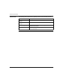
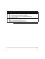
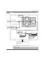
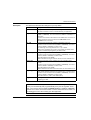
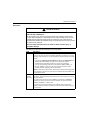
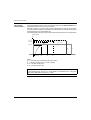
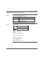
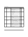
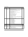
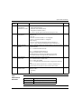
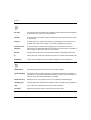
%S4
%S5
%S6
%S7
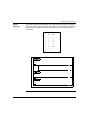
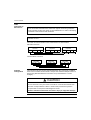
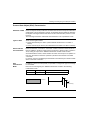
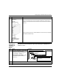
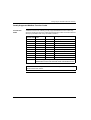
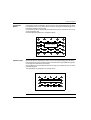
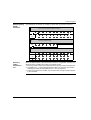
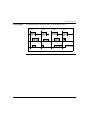
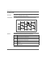
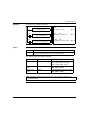
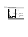
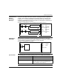
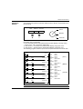
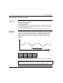
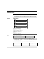
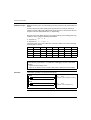
Time base: 10 ms
Time base: 100 ms
Time base: 1 s
Time base: 1 min
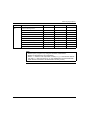
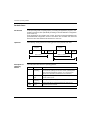
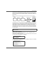
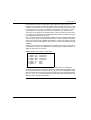
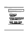
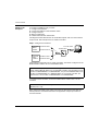
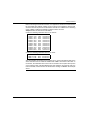
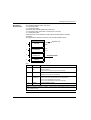
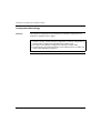
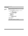
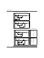
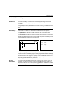
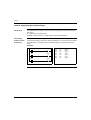
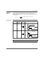
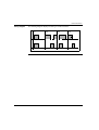
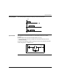
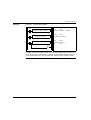
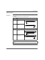
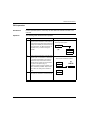
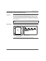
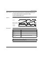
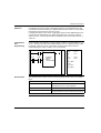
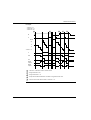
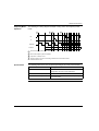
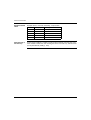
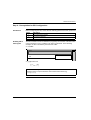
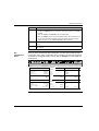
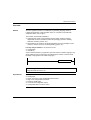
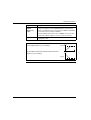
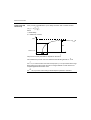
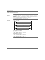
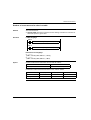
The rate of status changes is measured by an internal
clock. They are not synchronized with the controller
scan.
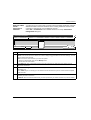
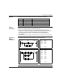
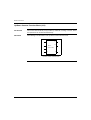
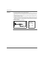
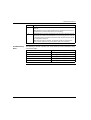
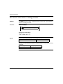
Example: %S4
5 ms 5 ms
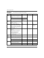
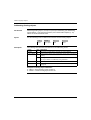
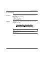
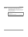
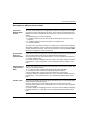
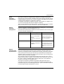
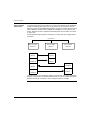
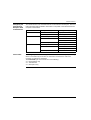
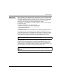
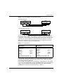
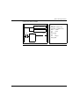
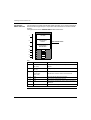
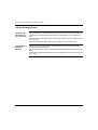
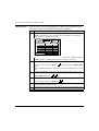
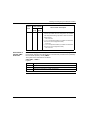
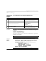
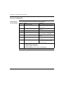
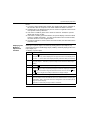
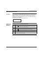
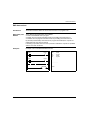
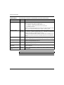
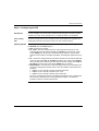
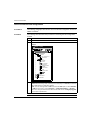
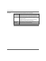
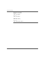
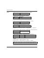
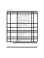
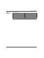
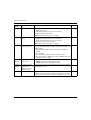
%S8
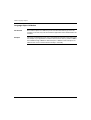
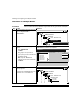
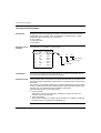
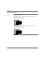
Wiring test
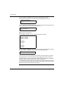
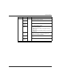
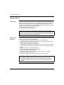
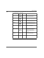
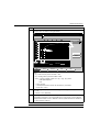
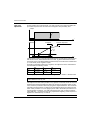
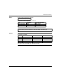
Initially set to 1, this bit is used to test the wiring when
the controller is in "non-configured" state. To modify
the value of this bit, use the operations display keys to
make the required output status changes:
z Set to 1, output reset,
z Set to 0, wiring test authorized.
1
U
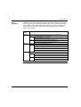
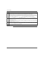
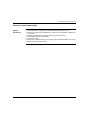
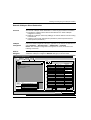
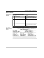
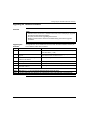
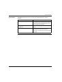
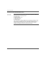
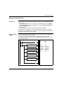
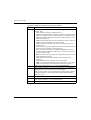
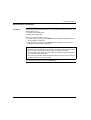
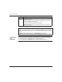
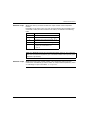
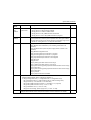
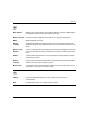
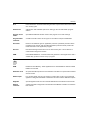
%S9
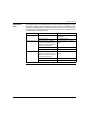
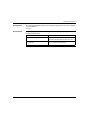
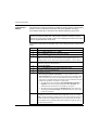
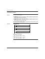
Reset outputs
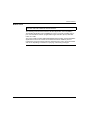
Normally set to 0. It can be set to 1 by the program or
by the terminal (in the Animation Table Editor):
z At state 1, outputs are forced to 0 when the
controller is in RUN mode,
z At state 0, outputs are updated normally.
0
U
596
TWD USE 10AE