1
6. FINAL TESTING PROCEDURE
NOTE:
a) Turn on the key, insert the back gear. In a fraction of second the control
unit performs a check of the functionality of the system and, if everything
has been done correctly, the transducer emits an acoustic sound of "OK"
(two notes in rapid succession). Once you have this signal the system
becomes operational.
- The distances will vary depending on the size of the obstacle and
correspond to the central zone of the bumper; on the lateral edges the
distances is less (see Figure 6)
- The alert occurs only when the vehicle is approaching an obstacle, a
fixed object in front of the bumper is only detected after the first
movement of approach.
Possible problems and their solutions
WARNING
1. In presence of rain or high moisture weather, the system reduces his
1. If the acoustic transducer does not emit any signal check all the sensibility automatically in order to eliminate a part of false alarms that
connections.
could be given by movement of water on the bumper.
2. If the transducer emits an audible warning signal consisting of 2 notes
(one high and one low) repeated 3 times) check the connection of RF 2. As soon as the system is activated an acknowledgment of the
cable.
surrounding of the bumper is made.
Consequently it is very important, during testing operation, not to
b) Starting from about 1 meter away from the center of the bumper, slowly switch on the system while you are very close to the central unit and
approach both hands to simulate a parking maneuver. At a distance of antenna sensor in order not to have false information on the working
about 60/70 cm will be heard the first acoustic signals whose repetition capability of the system
rate will increase at the decreasing distance to become a fast intermittent During the test you must also take into consideration the fact that, after
sound fast and then a continuous higher frequency sound at about 10-15 the first approach to the bumper, any subsequent APPROACH without
cm from the bumper.
first reset the system , can give false interpretations of the functionality
of the sensor due to special characteristics of the PD1 REAR
WARNING: For a correct simulation be careful to reset the system every software specifically created to reduce false signaling in the rainy
time you approach.
conditions.
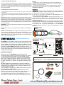
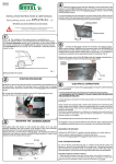
ALERT ZONE
c) If the system shows to work regularly it is possible to fix definitely the
bumper.
ALARM ZONE
CONTACT RISK ZONE
NOTE: the PD1 REAR start to give the signaling only when the
vehicle is being approached to the obstacle; a fixed object in front
of the bumper, for instance the hauls hook and a bull bar or the
sides walls of a car box, is not signaled and it is not bothered the
normal operation of the device
USER MANUAL
Fig. 6
(OPERATING PRINCIPLE)
PD1 REAR is an innovative parking sensor that uses low energy
electromagnetic waves and is able to detect the approach of any
kind of obstacle . The activation of the device is obtained by the
insertion of the back gear and confirmed by a signal of “OK". Once
activated, the PD1 REAR generates around the bumper, on
which is installed, a protection zone (Fig. 6). When any obstacle
present in the protection zone tends to approach the bumper you
will hear a series of beeps.
WORKING EXAMPLE
A) As soon as the PD1 REAR is activated the control
functionality of the system is carried out in a fraction os second.
In case of anomalies the speaker emits an audible warning
signal consisting of 2 notes (one high and one low) repeated 3
times. If this happens check the antenna connection to the
ECU. If the control is OK you hear a signal of two notes
in rapid succession to confirm the proper functioning of the
system.
B) When approaching an obstacle the system activates the
acoustic signal at a distance between the bumper and obstacle
(measured in the central area of the bumper) of about 60 / 70
cm with 3 types of sounds:
1) an increase in sequence of "BIP" (alert) informs the driver
that an obstacle is approaching.
2) intermittent sounds of fast repetition rate when the
obstacle comes close to the bumper at a distance between 15
and 30 cm measured on the middle of bumper (alarm).
3) continuous sound at a more low frequency (risk of contact) when an obstacle is very close to the bumper (10-15 cm).
Block Schematic
TECHNICAL CHARACTERISTICS
- Operating range from 9,5 to 18V - Operating temperature from -20 to +90 °C
- Max current absorption
70 mA - Averange distance to begin detection 70-80 cm
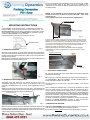
Buzzer Cable
RF Cable
Buzzer
Power Cable
Sticking material
Antenna sensor
Central unit