1
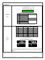
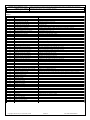
Connections
GROUND
5
10V - 18V DC
Input Contact 25
4
PTT Contact N.O.
Right Speaker -
3
Input Contact 26
Right Speaker +
2
PTT Contact COM
Left Speaker -
MAIN
Left Speaker +
Pin #
1
2
3
4
5
6
7
8
9
10
Speaker and Power
Connector
1
6
7
8
9
10
Signal
Left Speaker +
Left Speaker Right Speaker +
Right Speaker Input Contact 25
Input Contact 26
PTT Contact COM
PTT Contact N.O.
10VDC – 18VDC
Ground
Filename
19C.WAV / 19O.WAV
1AC.WAV / 1AO.WAV
Mating Connector: 10-position removable Terminal Block (included)
PIN
1
2
3
4
5
6
7
8
9
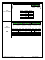
Serial
Connector
DCE
Signal
JB1 as DCE
Direction
DTE
Signal
JB1 as DTE
Direction
RS-485 BRS-232 TxD
RS-232 RxD
I/O
OUT
IN
RS-485 BRS-232 RxD
RS-232 TxD
I/O
IN
OUT
GND
RS-485 A+
RS-232 CTS
RS-232 RTS
+12-15VDC
PWR
I/O
IN
OUT
PWR
GND
RS-485 A+
RS-232 RTS
RS-232 CTS
+12-15VDC
PWR
I/O
OUT
IN
PWR
Mating connector: DB9 Female
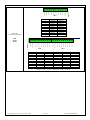
JB1 Serial Configuration Jumpers
RS-485
RS-232
DCE
JB1
JB1
JB1
JB1
DTE
RS232
DEFAULT in copper traces
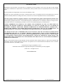
The board is configured as RS-232 DCE to allow use of a 1 to 1 cable between the CFSound
and a PC. This configuration is established by copper jumpers on the bottom of the board between
the JB1 pins.
Copyright©1998-2015 by ACS, Sarasota, Florida
2 of 13
ALL RIGHTS RESERVED