1
Contents
1
1.1
1.2
1.3
1.3.1
1.3.2
1.3.3
1.3.4
Overview
Installation - General Notes
Wiring Guidelines to Minimise the Effects of EMI
Electrical Installation - General Notes
Operation with Unearthed (IT) Supplies
Operation with Residual Current Device (RCD)
Installation After a Period of Storage
Operation with Long Cables
6
7
8
10
10
10
10
11
2
2.1
2.2
2.2.1
2.2.2
2.2.3
2.2.4
2.2.5
2.2.6
Installation – MICROMASTER Vector
Mechanical Installation
Electrical Installation
Power and Motor Connections - Frame Size A
Power and Motor Connections - Frame Size B
Power and Motor Connections - Frame Size C
Control Connections
External Motor Thermal Overload Protection
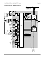
Block Diagram – MICROMASTER Vector
12
12
15
17
18
20
22
23
24
3
3.1
3.2
3.2.1
3.2.2
3.2.3
3.2.4
Installation – MIDIMASTER Vector
Mechanical Installation
Electrical Installation
Power and Motor Connections
Control Connections
Motor Overload Protection
Block Diagram – MIDIMASTER Vector
25
25
28
29
30
30
31
4
4.1
4.1.2
4.2
4.2.1
4.2.2
4.2.3
Controls and Basic Operation
Controls
DIP Selector Switches
Basic Operation
General
Initial Testing
Basic Operation – 10 Step Guide
32
32
33
34
34
34
35
5
5.1
5.2
5.3
5.3.1
5.3.2
5.3.3
5.4
5.5
Operating Modes
Digital Control
Analogue Control
Motor Control Modes
Linear Voltage to Frequency (V/f) (P077= 0 or 2)
Flux Current Control (FCC) Operation (P077 = 1)
Sensorless Vector Control (SVC) Operation (P077 = 3)
Stopping the Motor
If the Motor Does Not Start Up
36
36
36
36
37
37
37
38
38
© Siemens plc 1999
G85139-H1751-U529-D1
4/8/99
2