1
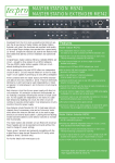
MASTER STATION MS745
1
2
19
3
4
5
18
6
17
7
8
9
10 11
12
13
14
16 15
Front Panel Features
1
Power ON / OFF Switch
11
Sidetone B - When a headset is plugged in, the level of the
user’s voice can be adjusted in relation to other operator’s voices
on this intercom circuit.
2
Remote Mic Kill - Shuts down all open microphones on a
selected circuit.
This feature is not compatible with original Tecpro designs which use
mechanical switches.
All Series 2 products use electronic switching and will respond to ‘RMK’
12
Phones Level - Adjusts headset listening level
3
Circuit A Select Button
13
Mic - Switches headset microphone on and off.
Latching and non-latching modes.
4
Call A - When Circuit A is selected, pressing the Call button
makes all Call lights on that circuit illuminate.
14
Headset Input / Output - Plug headset in here
5
Call B - When Circuit B is selected, pressing the Call button
makes all Call lights on that circuit illuminate.
15
B - Indicates auxiliary selected for circuit B.
6
Circuit B Select Button
16
A - Indicates auxiliary selected for circuit A.
7
Aux Selector Switch - Directs auxiliary audio to circuit A, B,
A and B or none,
17
Overload B - Indicates excessive current draw on circuit B
intercom line.
8
Aux Level Control - Controls the level of the auxiliary signal.
18
Overload A - Indicates excessive current draw on circuit A
intercom line.
9
Circuits Independent / Link B to A - Using the toggle switch,
circuit B may be linked to circuit A to form a single ‘super’ circuit
with double the drive capacity .
19
Front Panel - Brushed, anodised aluminium curved extrusion.
10
Sidetone A - When a headset is plugged in, the level of the
user’s voice can be adjusted in relation to other operator’s voices
on this intercom circuit.