1
38
Commands
in the simulation
context
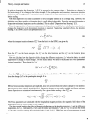
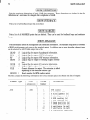
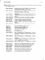
can be printed with the command SHOW-MISALIGN. The command MDLERR allows to implement
errors that result from imperfections of the drive line for the RF triggers (see command).
5.9
RF
Trajectory feedbacks
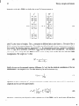
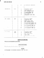
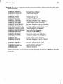
Feedbacks (compare section 3.11.6) can be defined at every marker point (compare section 8.1) using the command DEFINE-FEEDBACK.
The feedback setpoints are set and reset with the command
SET-FEEDBACK. This command also allows to change the active plane of a feedback (’ X’ , ’ Y’ , ’BOTH’ ,
‘NONE ) giving the possibility to switch off feedbacks. A list of feedbacks is printed from the command
SHOW-FEEDBACK. The command FDBK-MISAL references the feedbacks to the BPM misalignment (as
in an actual feedback where the BPM readings are fitted). The feedbacks can be golded using the command
FDBK-GOLD, which means that the feedback reference information is updated to the actual trajectory offsets at the feedback marker point.
5.10
Multi-device
knobs
Multi-device
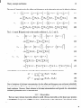
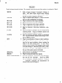
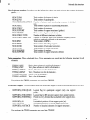
knobs (e.g. N corrector closed bumps) can be defined with the command
DE- .
FINEMULTIKNOB.
Devices that can be specified within a multi-device knob include quadrupoles, RF
structures and dipole correctors. Parameters that can be changed include transverse misalignments, magnetic
fields, longitudinal rotation angles, RF phases and gradients. The value of a multi-device knob is changed
with the command SETMULTIKNOB.
Existing multi-device knobs can be displayed using the command
SHOW-MULTIKNOB.
_-
5.11
Tracking
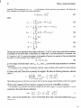
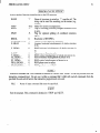
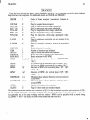
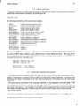
When the relevant pieces of information are set up, the command TRACK will track the beam through
the beamline. During tracking the bunch positions, the emittances, the BMAG’s and the luminosity reductions are calculated and saved for all regular BPM’s. The RF BPM’s at the beginning and the end of each
structure are updated with the beam position. Tracking can be done in first or second order, coupled or uncoupled, with or without the different types of wakefields by specifying the different command parameters.
It is recommended always to call the simple TRACK command once after setting up the simulation. The
specified options will set up defaults that are used by some correction commands (e.g. by the tracking part
of QALIGN). After tracking is done, the command TRAJFIT can be used to fit the beam offset and angle at
a specified BPM, using a number of downstream BPM readings.
5.12
Correction algorithms
Two families of correction algorithms are available. There are procedures that do not include tracking.
CORRECT performs a l-to-l correction by solving a least-squares problem for the BPM’s of the whole
linac (compare section 3.11.1). The dipole correctors are adjusted accordingly. One needs to call the tracking
routine afterwards. CORRECT assumes that exactly one downstream BPM (next QF) is associated to every
dipole corrector (this QF). The command might fail if the lattice is not set up properly. Positively charged
particles are handled by the command CORRECTP. RFALIGN realigns the RF structures using movers at
the two support points of the common girder (compare section 3.11.2). Tracking needs to be called before
and after this command.
Another family of commands includes the tracking part. TRACKC will track the beam through the lattice
and do a l-to-l correction on the fly (compare section 3.11.1). This is a fast and easily converging correction
algorithm.
The l-to-l correction assumes that exactly one downstream BPM (next QF) is associated to