1
2-2 Setting the Pavement Thickness and Estimated Pavement Thickness
In the past, a measuring device known as a depth gauge was used.
The operator would insert the gauge stick into the pavement and measure.
This has been replaced by a contactless measuring system which
simultaneously displays the depth digitally for the operator and also
displays a graph of the transition in the pavement thickness.
In addition, it was difficult in the past to know how the pavement
thickness would change over time, but with the new machine, sensors are
used to determine automatically the condition of the base course which is
being paved as well as movements of the screed and display an estimated
pavement thickness. These data are displayed in real time on a color
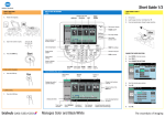
display at the control panel, as shown in Picture 1.
The layout diagram of paving
thickness measuring device and a
block diagram are shown in Figure 3
and Figure 24
The theory used for measuring the
pavement thickness is as shown below.
[State 1]
sew.:.--4a-3OI
Inclination Sensor
Measuring Arm 11 _ "'
I
Ir
To measure the paving thickness T
when the screed is in position B (when
the machine position is in state 2),
first measure the difference 8 between
the valleys and peaks in the base course
at points B and C with the machine
position in state 1.
Since H1 + 8 = H2 + M tan 0,
8 = H2 - H1 + M tan B.
In the right figure, the formula is
given below.
H2' + 8 = Hp + T + T tan U'
[State 21
D
B
C
According to this formula, the
paving thickness at point B can be
calculated to be
T = H2' + 8 - M tan 0' - HD
(B:Determined from the previous formula)
Furthermore, at this time, since 82 is measured and calculated as
shown in the above figure, if the screed is moved to point C, next time
it will be possible to measure and calculate the pavement thickness at
point C.
Displayed at
Operator's Seat
Computer
Measuring
Road Surface (Reference)
nclination Sensor
Figure
3
Layout of Pavement Thickness Measuring
and Display Device