1
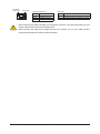
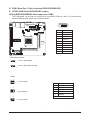
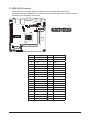
22) F_PANEL (Front Panel Header)
Connect the power switch, reset switch, speaker, and system status indicator on the chassis to this
header according to the pin assignments below. Note the positive and negative pins before connecting
the cables.
Pin No.
1
2
3
4
5
6
7
8
9
10
Signal Name
HD+
MPD+
HD-
GND
GND
PW+
RST+
GND
NC
NC
2
10
1
9
Definition
Hard Disk LED Signal anode (+)
Power LED Signal anode (+)
Hard Disk LED Signal cathode(-)
Ground
Ground
Power Button anode (+)
Reset Button
Ground
No connect
No Pin
The front panel design may differ by chassis. A front panel module mainly consists of power switch,
reset switch, power LED, hard drive activity LED, and etc. When connecting your chassis front
panel module to this header, make sure the wire assignments and the pin assignments are matched
correctly.
- 25 Hardware Installation