1
4. OPERATION
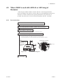
Remove the amplifier unit from the converter.
• How to remove the amplifier unit (AXFA14 and AXF integral flowmeter are same procedure).
See IM 01E20D01-01E regarding the procedure of removing amplifier unit.
(1) Turn off the power.
(2) Loosen cover locking screw, and remove the cover.
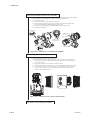
(3) Remove wiring connectors 1 and 2 (refer to Figure 4.8.2) from the amplifier unit.
Remove them carefully, without applying excessive force.
(4) Loosen the three mounting screws while holding the unit with your hand.
(5) Pull the unit straight out.
Wiring connector 1
Amplifier mounting
connectors
Wiring connector 1
Amplifier mounting
screw (three units)
Rod
Wiring connector 2
Wiring connector 2
Figure 4.8.2 Removing / Assembling the Amplifier
Place the amplifier unit in the junction box.
• Only the amplifier is housed in the junction box.
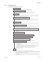
(1) Insert the connector pins of the amplifier into the two connectors on the terminal
board of the junction box, aligning the holes of the plate with the positioning pins as
shown in the figure.
(2) Engage the connectors to the amplifier. (See Figure 4.8.3.)
(3) After checking that the connections are secure, firmly tighten the fixing three screws.
(4) Screw in the cover firmly as shown in Figure 4.8.3 where general-purpose use and
sanitary type is shown. In case of explosion proof type, use the cover of 10mm
thickness into amplifier unit side.
GLASS:10mm
GLASS:3mm
Figure 4.8.3 Setting Converter Unit in Junction Box
Proceed to 4.8.2 Checking Procedure.
4-19-6
IM 1E6K2-E