System Block Diagram:
Connections and Indicators:
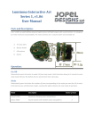
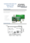
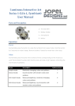
Top View
A. Switched Auxiliary
Output
B. Remote Enable
C. +12V Input
D. +12V Input
E. Ground
F. Ground
G. +5V Output
H. +5V Output
I. +5V Output
J. Output Power ON
K. Alarm Condition
Indicator
L. USB Enable
M. ATC Fuse