1
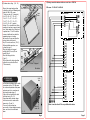
B) Fixation under ceiling : ( Pic. 10 )
C)Driving several fan heaters with one control box - A750790
Ceiling or horizontal
7
support
- Choose the support angle position
in fixing the cross bar in following holes
thanks to 2 M8 x 120 screws :
7.3 w/o cross bar = 0° ( horizontal )6.8 = 20° - 6.9 = 30° - 7.8 = 40° 9
7.9 = 43° - 7.1 = 57° - 6.1 = 58° 8
7.2 = 67° - 7.3 = 72° - 7.4 = 78° 6.2 = 80° - 6.3 = 90° ( vertical ) .
Position 7.3 is not suitable for ceilling
mounting but only on a support at more
than 1 meter down to the ceilling level.
In position from 7.1 to 6.3 the heater
becomes stratificator free and offers
important runing costs cutings .
- Unscrew the 4 screws and place the
pivot on the top of the heater
Rep. D then rescrew them . ( Pic11 ).
Pic. 10
- Further intallation procedure, see
section A of page 3 .
- Place the heater on its support
A
and tight the M12 screw (19 mm
wrench) Rep. A.
D
- Place the blocage clutches
C
( Rep. C ).
- Fix the heater in the desired position
tighten the screw A and the B nut
B
( 10 mm wrench).
Pic. 11
3
4
6
230 mono - Tri 230+N - Tri 400V+N
5
Cable
inlets
2
1
Control boxes
E
D
C
B
A
Thermostat
Fan heater N°1
B1
D
C
L1
L2
B
A
B
C
Pivot
Support
D
Fan heater
E
Fan heater N°2
4- WIRING AND
CONNECTION
- All fan heater installation shall be made
in accordance to the C15-100 norms
the section and protection of the power
cord wires must be in accordance to
the intensity board of page 5.
- Cables inlets are located at the back
of the fan heater ( Pic. 12 ).
- Connection and the tension change
of the heater must be conducted as
shown in pic. 13 and 14.
- To access to the junction box,
unscrew the 4 screws without removing
them, and sleeve the mobile hood
down .
Cable
inlets
B1
L1
L2
A
B
C
D
E
Same connection than N°2 for any additional fan heater
Mobile
hood
Pic. 12
Page 4
Page 9