1
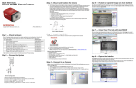
Step 9 — Set Camera Parameters
Step 12 — Run the Job
1. Click on the Camera box to the left of the image area.
2. In the camera parameters below the image area, select the desired type of Trigger, Trigger Polarity,
Photometry (Exposure and Gain), Focus, and Lighting.
When all job parameters are set, click on the Run step at the top of the interface. The software will download the
vision job just created to the camera and will begin the inspection. Inspection results and the list of active tools
are shown at the right of the image view. That information can also be moved below the image area by
clicking the orientation buttons above the inspection results area.
Power Requirements and Pin Assignments
Power Requirements: 5VDC +/– 5%, 200 mV p-p max. ripple, 554 mA @ 5VDC (typ.)
Vision MINI USB and I/O connectors
15-pin D-sub
I/O Connector
USB Type B
Connector
Vision MINI Connector Schematic
USB Type B
Connector
D-sub I/O
Connector
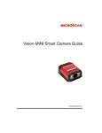
Vision MINI Smart Camera Accessories
Step 10 — Add Tools to the Job
Test Jobs
1. Click on the Decode Tool or drag it onto the image area.
2. Use the anchor points at the corners of the region of interest to form a box around the Data Matrix
symbol. Leave plenty of space on each side of the symbol.
3. Now add a second Decode Tool and do the same for the 1D symbol below the Data Matrix symbol.
4. Finally, add an OCR Tool and drag the region of interest around the area of the image where “123456”
is printed.
Note: For descriptions of more advanced functionality, such as setting Inspection Outputs or using the
Locate Tool and Decode Tool’s Dynamic Locate functionality to track multiple tools from image to image,
see the help documentation in AutoVISION software or the AutoVISION User’s Manual.
Decode Tool, OCR Tool, Match Strings Tool,
String Format Tool
Communication and I/O Devices and Cables
IC-332 Adapter
FIS-0001-0035G
Connects the camera to an IB-131 interface device.
Provides 5VDC power and optoisolation for the camera.
MS-Connect 210
FIS-0210-000XG
Connectivity box
USB Type A to USB Type B Cable, 6’
60-000064-01
Connects camera cable to host.
Trigger
99-000017-01
Photo Sensor, Visible, NPN, Dark On
Trigger (MS-Connect 210 configuration) 99-000017-02
Photo Sensor, Visible, NPN, Light On
Trigger (USB configuration)
99-000019-01
Photo Sensor, Visible, NPN, Light On
IB-131 Interface
99-000018-01
Allows cameras to be connected easily to power, trigger,
and standard serial connections.
Host Cable
61-000105-01
MS-Connect 210 to Host, User-stripped to 9-pin
Camera Cable
61-000127-01
Camera to MS-Connect 210, 6’ (1829 mm)
Communication Cable
61-300026-03
DB25 Plug to DB9 Socket, 6’ (1829 mm)
97-100004-15
90-264 VAC, 24VDC, USA/Euro plug
Mounting Arm Kit
98-000048-01
An adjustable mounting arm with ball and socket
connections that allow the arm to be positioned in
almost any orientation.
Extension Joint Kit
98-000053-01 (4”)
98-000053-02 (3”)
Allows the mounting arm to be extended. Kits include
extension joint and mounting arm.
Base Plate Kit
98-000054-01
Plate for desktop presentation, 6” x 6” (152.4 mm x 152.4
mm).
Power Supply
Power Supply
Mounting Options
Measure Tool,
Count Tool
Step 11 — Try Out the Job
Once you have configured the tools as desired, use the arrow icons in the Job area to try the job you have
just created.
Note: Most jobs will inspect multiple captured images. If only one image is being inspected, the effect of the
arrow icons will not be evident.
Try Out Job
Once
Try Out Job
in Loop
Through-Hole Mount Bracket
98-000057-01
Allows the camera to be mounted to various surfaces.
Side Mount Bracket
98-000060-01
Allows the camera to be mounted at a 90° angle.
Right-Angle Mirror Kit
98-000088-01
Changes field of view direction by 90°.
Diffuser Accessory Kit
98-000098-01
Improves readability of direct part marks.
98-000215-01
Carrying case, mounting blocks, mounting rods, power
supply, IC-332, IB-131, cables, test cards, documentation.
37-000010-01
Software, User’s Manuals, Quick Start Guides,
Configuration Guides, links to other documents on
Microscan website
Demo Kit
Demo Kit
Documentation
Microscan Tools Drive
Note: Additional accessories are available in the Microscan Product Pricing Catalog.
Vision MINI Part Numbers
Vision MINI part numbers follow the format GMV-6300-CLSYG:
Comm = 2 for USB;
Lens = 1 for Standard Density, 2 for High Density 2.5;
Sensor = 1 for SXGA (1 megapixel), 2 for Color QXGA (3 megapixel);
Y (Options) = 0 for AutoVISION, 1 for Custom, 2 for Licensed (Visionscape), 3 for Custom + Licensed
G = RoHS-Compliant
Copyright ©2011 Microscan Systems, Inc.