1
®
®
Certificate of Calibration
We hereby certify that this product has been calibrated
and found to be in accordance with the applicable
SPECIFICATIONS and STANDARDS.
Accuracies of the standard equipment used in
this calibration are traceable to the National Standards.
MECO METERS PVT. LTD.
Plot No. EL-60, MIDC Electronic Zone,
TTC Industrial Area, Mahape,
Navi Mumbai - 400710 (INDIA)
Tel : 0091-22-27673311-16, 27673300 (Board)
Fax : 0091-22-27673310, 27673330
E-mail : sales@mecoinst.com
Web : www.mecoinst.com
SR. NO.
:
CHECKED BY :
DATE
:
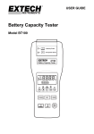
BATTERY CAPACITY TESTER
MODEL : 6363
MODEL NO.
:
USER MANUAL
CONTENTS
1.
FEATURES ..................................................................... 3
2.
NAMES AND FUNCTIONS OF PARTS ....................... 3
3.
SPECIFICATIONS .......................................................... 6
1.
FEATURES
l
The Battery Tester is designed for measuring, the
internal impedance and open - circuit voltage of the
secondary battery including lead storage cell. nickelcadmium battery, lithium-ion battery and nickel-metal
hydride battery.
l
AC four-terminal method to measure the internal
impedance by eliminating lead impedance and contact
impedance to get the accurate results.
l
Dual - display to show the internal impedance and voltage
of the battery simultaneously.
l
It has 99 sets of composite comparator function, which
can be set at impedance and voltage values to get the
reliable detection of battery deterioration.
l
Pin type leads, which can easily contact the battery
electrodes supplied as standard to get more accurate
4-terminal measurement.
3-1 General Specifications ........................................... 6
3-2 Electrical Specifications ......................................... 8
4.
OPERATION ................................................................... 9
4-1 Preparation ............................................................. 9
4-2 Operation ................................................................ 9
4-3 Zero Adjust (REL) ................................................ 10
5.
USING COMPARATOR FUNCTION (99 SETS) ....... 11
5-1 Comparator .......................................................... 11
5-2 Comparator Settings ............................................ 11
5-3 Comparator Tables .............................................. 12
5-4 Start / Stop Controls the Comparator .................. 13
6.
START / STOP DATA LOGGING .............................. 13
2.
NAMES AND FUNCTIONS OF PARTS
6-1 Erasing Memory ................................................... 13
13
6-2 Manual Data Logging (500 sets) ......................... 13
14
12
6-3 Continuous Data Logging .................................... 14
7.
MAINTENANCE ........................................................... 14
7-1 Cleaning ................................................................ 14
7-2 Battery Check & Replacement ............................ 14
8.
RS-232 INTERFACE, SOFTWARE INSTALLATION
and OPERATION ......................................................... 15
11
10
4
5
3
9
7
8
6
2
1
15
2
3
MODEL 6363 : DATED 25 04 2012
KEYS AND INPUT / OUTPUT TERMINALS
1.
Power key : Power on / off
10.q key : Press q key to decrease the displayed value.
11.⊳
2. R READ key :
l
Press R key to show the manual logged readings.
l
Press R READ key again to stop reading.
3. M MEMORY key :
l
Under the manual logging mode, the tester stores
each single set of logged reading to the memory
by pressing M MEMORY key.
l
Press and hold M MEMORY key for 2 seconds to
enter continuous logging mode. Press again to stop
logging.
l
key
Press ⊳ key to move the cursor to the left.
l Press
key to turn the beeper on or off.
12. RS-232 connector : PC interface connector.
13. - Input jack : For connecting with the black test lead
plug.
14. + Input jack : For connecting with the red test lead plug.
15. External DC Input
DISPLAY
4. V-RANGE key : Select the voltage range. (4V, 40V)
5. HOLD key :
l
Press HOLD key to freeze or unfreeze the
displayed reading.
l
Press and hold HOLD key for 2 seconds to enter
the interval lime setting mode for continuous data
logging.
6. RANGE key : Select the impedance range. (40mV,
400mV, 4V, 40V)
7. u REL key :
l
Press u key to move the cursor to the right.
l
Press REL (Relative) key to zero the reading,
1. The reading of the measured impedance (High or
Low limit of impedance on the comparator settings)
2. The reading of the measured voltage (High or Low
limit of voltage on the comparator setting).
3. The assigned number of comparator : 99 sets
4. The location for the manual logged data.
mV : The unit of impedance.
8. p key : Press p key to increase the displayed value.
V : The unit of voltage.
9. SET key :
l
l
4
COM : The symbol will appear when the comparator
function is on.
Press and hold the SET key for 2 seconds to enter
the comparator-setting mode. Press again to store
the setting in memory.
DATA R : The symbol will appear when the meter
start manual datalogging function or reading the manual
logged data.
M : Memory symbol for continuous datalogging
function.
The symbol will flash when each data is stored to the
memory.
INTV : Interval time settings of continuous datalogging
function. (1-255 seconds).
COMP.SET : Comparator settings.
HIGH : High limit setting of the comparator impedance
& voltage.
LOW : Low limit setting of the comparator impedance
LED Display
PASS (Green LED) : To indicate the tested battery
complies with the high limit of comparator.
WARNING (Yellow LED) : To indicate that the tested
battery is going to deteriorate.
FAIL (Red LED) : To indicate that the tested battery,
has deteriorated.
These indications will appear when the High and Low
comparator limits for internal impedance and the
comparator threshold value for voltage are all set.
3. SPECIFICATIONS
3.1 General Specification :
l Measuring method : Impedance (AC four-terminal
method).
l AID conversion : Dual slope method.
l Display : Dual display LCD and LED for (comparator
output).
l Sampling rate : 1 set of (impedance and voltage
measurement) / second.
l Open-Circuit terminal voltage : 3.5Vpp max.
6
HOLD : Hold-function.
Press SET key to switch the comparator mode on
or off.
: Low-Battery Mark.
: The symbol of beeper.
5
l
Input over range : “OL” display.
l
Low battery detection “
l
Test current fault detection : “- - - -” display.
l
Auto power off : Power off automatically after about 30
minutes.
l
Zero adjustment function : Circuit offset voltage is
displayed as 0V.
l
Hold function : Display is held.
l
Beeper function : Audible output for warning and fail results
(can be turned on and off).
l
Comparator settings : Impedance High and Low limits
and voltage throughold point.
l
Number of comparator settings : 99 sets.
l
Comparator output : LEDs for Pass (Green), Warning
(Yellow) and Fail (Red) results audible tone for warning
and fail results.
Resistance
” display.
Lo
IN
Hi
Lo
WARNlNG
WARNING
FAIL
Hi
PASS
WARNING
FAIL
Voltage
l
Manual Data logging : 500 sets.
l
Continuous Data logging : 9600 sets.
l
Operating environment : 0 0 C to 40 0 C 80%RH
(no condensation)
l
Storage environment : -10 0 C to 50 0 C 80%RH (no
condensation)
l
Power source : Six AA size 1.5V batteries. [AC adaptor
(output 9VDC) is optional].
l
Maximum power consumption : 1.0VA
7
MODEL 6363 : DATED 25 04 2012
l
Continuous operating time : 7 hours approx.
l
Maximum altitude value usable : 2000m or less
Maximum Input Voltage : 50VDC maximum, No AC voltage
input, Between input terminals and ground, 60VDC and
AC maximum.
l
Size : 250(L)mm x 100(W)mm x 45(T)mm
l
Weight : 500g approx. (including batteries)
l
Accessories : Test Leads, Instruction Manual, Batteries,
Software CD.
l
Option : AC adaptor (9V DC output).
DANGER
Do not exceed the maximum permissible input voltage
measurement terminal. This could result in injury or
damage to the unit.
4
3.2 Electrical Specifications :
OPERATION
4.1 Preparation :
Conditions to guarantee accuracy
l
Temperature : 230C ± 50C
The following safety information must be observed to ensure
maximum personal safety during the operation of this tester.
l
Humidity: 80%RH or less (no condensation).
l
l
Zero adjustment : After zero adjustment for each range.
To avoid electric shock when replacing the batteries
first disconnect the leads from the object to be measured.
l
Impedance measurement
l
When replacing the batteries, do not install old batteries
with new ones and do not mix different types of batteries.
l
Check the battery polarity carefully when inserting
the batteries. Do not short-circuit used batteries,
disassemble them, or throw them in a fire. Doing so may
cause the batteries to explode.
l
Be sure to dispose of used batteries properly.
0
Temperature coefficient : (±0.1%rdg ± 0.5dgs)/ C
Measuring current frequency : 1Khz ± 10%
Measuring burden voltage : 1.5mVAC
Range Resolution Measurement Current
Accuracy
40mV
10mV
25mA approx.
400mV
100mV
2.5mA approx.
± 1% rdg,
4V
1mV
250mA approx.
± 10 dgts
40V
10mV
25mA approx.
l
1. Remove the battery cover.
2. Insert the batteries into the battery compartment.
4.2 Operation :
WARNING
l Do not attempt to measure DC voltage exceeding 50V.
Do not attempt to measure AC voltages. This could
result in injury or damage to the unit.
l Do not attempt to measure the voltage of a generator.
This would result in an AC voltage being applied to
the voltage generating output terminals, which is
dangerous.
Voltage Measurement
Temperature coefficient (±0.1%rdg ± 0.5dgts)/0C
Range
Resolution
4V
1mV
40V
10mV
Accuracy
± 1% rdg, ± 6 dgts
8
9
l
will be taken as zero and will be used to calibrate subsequent
measurements.
After measuring a high voltage battery, before
continuing to measure a low voltage battery first short
the measurement leads together. This will discharge
the DC elimination capacitor which is connected across
the leads. Otherwise an excess voltage may be applied
to the low voltage battery, which is dangerous.
1. Short the red and black test leads probe 4 terminals.
1. Connect the red test lead to the “+” jack and the black
test lead to “-”Jack.
2. Press power
key to turn on the tester.
3. Connect the red test probe to the positive battery terminal,
and the black test probe to the negative battery terminal.
2. Press REL key. The display shows R , then the
impedance and voltage value is zero, connect the test
leads probe to the battery to be tested.
3. The zero adjustment is valid only for the currently
selected, range as long as the power remains on.
5.
USING COMPARATOR FUNCTION (99 SETS)
5.1 Comparator :
4. Using V-RANGE and V-RANGE keys to select desired
voltage and impedance ranges.
5. Read the battery internal impedance and DC voltage
directly from the display.
Note : When the measured DC voltage or battery internal
impedance value is over range. “OL” is display. When
the AC test current fault, “- - - -” will be displayed.
4.3 Zero Adjust (REL) :
10
The zero adjustment function is to zero the range of
impedance and voltage. The reading during zero adjustment
The comparator function compares the measured values
with preset High and Low limit values for internal impedance
and voltage level, and determines the range that the
measurement should fall into. Then according to the following
conditions to light the corresponding LED, and sounds a
beeper under the WARNING and FAIL cases.
5.2 Comparator Settings :
1. Press and hold down the “SET” key for 2 seconds, the
display will show COMP.SET to enter the comparator
setting mode.
2. Use the p or q key to change the comparator number,
from 01 up to 99.
11
MODEL 6363 : DATED 25 04 2012
3. Use the V-RANGE or V-RANGE key to the battery
voltage and impedance to be measured range.
5.4 Start / Stop Controls the Comparator :
1. Press SET key to start comparator function; the COMP
indication will appear on the display, and the comparator
will be operating once the measurements are taken.
4. Press u key one time, the low limit impedance of the
“two higher digits” will be flashing. (Use the p or q keys
to select the desired value.)
2. Press p or q keys to select the desired comparator
number. The selected comparator number remains in
memory even the power is turned off.
5. Press u key one time, the low limit impedance of the
“two lower digits” will be flashing. (Use the p or q keys
to select the desired value.)
key to set the beeper on, the
indication will
3. Press
appear on-the display, and the beeper will sound when
getting the WARNING or FAIL result. Press key again
to set the beeper off.
6. Press u key one time, the high limit impedance of the
“two higher digits” will be flashing. (Use the p or q keys
to select the desired value.)
7. Press u key one time, the high limit impedance of the
“two lower digits” will be flashing. (Use the p or q keys
to select the desired value.)
8. Press u key one time, the throughold voltage of the
“two higher digits” will be flashing. (Use the p or q keys
to select the desired value.)
4. Press SET key again to stop comparator function.
6.
6.1 Erasing Memory :
When memory is full, “Full” symbol will appear on the
display and logging will be stopping.
1. Press
9. Press u key one time, the throughold voltage of the
“two lower digits” will be flashing. (Use the p or q keys
to select the desired value.)
10. Repeat step 2 to step 9 to set the next comparator
number.
6.2 Manual Data Logging (500 sets) :
1. Log the reading one by one to the memory by
pressing M MEMORY key, and “DATA M NO XXX”
will appear on the LCD for one sec. to indicate the
memorized location.
5.3 Comparator Tables :
Impedance
Low limit resistance
High limit resistance
Voltage
WARNlNG
Beeper
WARNING
Beeper
FAIL
Beeper
PASS
WARNING
Beeper
FAIL
Beeper
Comparison
Ò
Value
Middle
Ò
Ò
Lo
key to turn off the tester.
2. Press and hold M MEMORY key, then press
key
until the display shows Clr to delete all logged reading
in the memory.
11. Press SET key again to exit from comparator setting
mode.
Voltage
START / STOP DATA LOGGING
2. Press R READ key to review the logged readings.
The display will show “DATA R NO XXX”. Press
p or q keys to scroll through the logged readings.
Hi
3. Press R READ key again to stop viewing logged
readings.
12
13
6.3 Continuous Data Logging :
1. Press HOLD key for 2 seconds, the display will show
INTV. Using p or q key to select desired interval
time from 1 second to 255 seconds. Press SET key
to exit interval time setting.
2. Press M MEMORY key for 2 seconds to enter
continuous logging mode, the display will show M
Each flashing means the reading is stored to the
memory.
8.
RS-232 INTERFACE, SOFTWARE INSTALLATION AND
OPERATION
l
For the detailed instruction, please refer to the
content of attached CD-ROM, which has the
complete instruction of RS-232 interface, software
operation and relevant information.
l
RS-232 protocol are enclosed within the content
of CD-ROM, please open the CD-ROM for details,
3. Press M MEMORY key again to exit continuous
logging mode.
4. The continuous data logging can’t be read from the
tester directly. Users can read the data by
transferring to PC.
7.
MAINTENANCE
7.1 Cleaning :
1. Repairs or servicing not covered in this manual should
only be performed by qualified personnel.
2. Periodically wipe the case with a dry cloth.
Do not use abrasives or solvents on this instrument.
7.2 Battery Check & Replacement :
1. As battery power is not sufficient, the
will be
shown on LCD, To replace with six new 1.5V batteries
is required.
2. a). Disconnecting test leads.
b) Turning off the tester.
c) Open the battery cover with screw driver.
d) Replace the batteries
e) Cover and secure the battery cover.
14
15
MODEL 6363 : DATED 25 04 2012