1
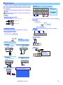
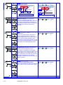
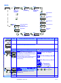
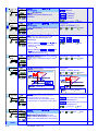
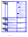
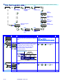
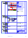
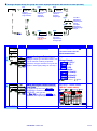
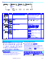
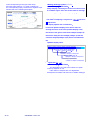
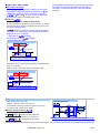
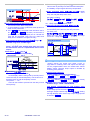
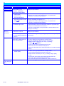
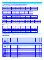
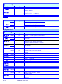
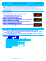
Wiring Diagram Please check the voltage of power supplied first, and then connect to the specified terminals. It is recommended that power supplied to the meter be protected by a fuse or circuit breaker.。 Remark,PT can not short in secondary;CT can not open in secondary Wiring may be changed, follow the wiring diagram on theinstrument wiring Terminals Terminals: 2 20A/600Vac, M3.5, 1.2~3.5mm (22~12AWG) 9 10 11 12 13 14 15 16 1 2 3 4 5 6 8 Power&Input Terminals AC115V AC230V AXU.Power Input Signal 20A/300Vac, M3.5, 12~22AWG; Max torque: 13Kg-cm 7 Option output terminal If power supply noise interference, install an isolation transformer.。 (If the use of electric driver, please adjust the torque electric driver) 7.0mm max 7.0mm max Input Signal Connection Output (one output available of Relay, Analogue or RS485) Connect the input signal, use twisted-pair isolation。 Relay output RELAY 1 b c a RELAY 2 b c a 9 10 11 12 13 14 15 16 Analogue Output CM1-PR Input Connection 2-wire sensor transmitter connection 4(0)~20mA Input Connection 24Vdc 4~20mA Input EXCIT.Power 1 2 3 9 10 11 12 24Vdc 4~20mA Input EXCIT.Power 4 5 1 2 3 RS485 port 4 5 A 9 10 11 12 4~20mA 3-wire sensor transmitter connection 1 2 3 Max. Distance: 1200M Terminate Resistor (at latest unit): 120~300ohm/0.25W (typical: 150ohm) 0~10V Input Connection EXCIT.Power 0~10V Input 4 5 1 2 24Vdc 0~10V Input B Vo 0V +V 24Vdc EXCIT.Power 3 4 5 0~10V Sensor Input Connrction DIP switch to switch the input mode and pulse level but must beconsistent with the input signal 3 0V +V +IN 1 2 +Vdc Out 0V DIP D-S NPN PNP CONTACT 1 2 3 ON ON ON Voltage pulse 5VP Voltage pulse 12VP Voltage pulse 24VP 4 5 ON ON ON DIP switch position cut to the bottom, behalf the DIP switch is ON CM1-SERIES 2012-11-08 3 / 27