1
METHOD A:
B O LT S
METHOD B:
FRAME INSERTION
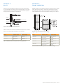
When mounting PV modules with bolts, the mounting holes located
on the rear flange of the frame must be used. Use either ¼ inch or M6
stainless steel bolts, nuts and washers. The bolts should be torqued to
racking/mounting manufacturer’s specifications.
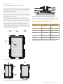
Module frames can be supported by insertion systems where the module
frame rests inside of a channel. The channels are required to support
the entire length of either both of the long frames or both of the short
frames. Module frames must be restricted from vibrating in the channel.
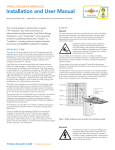
PV Laminate
Aluminum
Frame
Backing Nut
Toothed Lock Washer or KEPS Nut
Equipment
Grounding
Conductor
Grounding Lug
Screw
Figure 2: Detail of a bolt mounting attachment
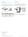
Table 1 includes a list of maximum allowable load pressure for modules
that are mounted with bolts through the mounting holes.
Figure 3: Long side and inside insertion mounting
Series
Attachment Location
Maximum Load (Pa)
Series
Attachment Location
Maximum Load (Pa)
YGE 60 Cell
4 bolts at each of the
mounting holes
2400 upward, 2400
downward
YGE 60 Cell
Two channels that support
both long frames
2400 upward, 2400
downward
YGE 72 Cell
4 bolts at the outer
mounting holes
2400 upward, 2400
downward
YGE 60 Cell
Two channels that support
both short frames
1900 upward, 1900
downward
YGE 72 Cell
Two channels that support
both long frames
2400 upward, 2400
downward
YGE 72 Cell
Two channels that support
both short frames
1900 upward, 1900
downward
Table 1: Allowable maximum load pressure for mounting with bolts
Table 2: Allowable maximum load pressure for insertion mounting
Yingli Solar PV Modules, Mounting Guide / page 2