1
Control Moment Gyroscope - ECP Model750
The Utility menu contains the
following pull-down options:
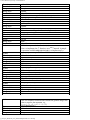
Configure Optional auxiliary DACs
Jog Position
Zero Position
Reset Controller
Rephase Motor
Down Load Controller Personality
File
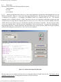
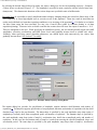
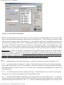
2.1.9.1 The Configure
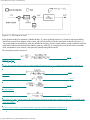
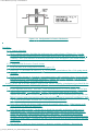
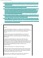
Auxiliary DACs dialog box (see
Figure 2.1-11) enables the user to select various items for analog
output on
the two optional analog channels in front of the ECP Control Box. Using equipment such as an oscilloscope,
plotter, or spectrum analyzer the user may inspect the following items
continuously in real time:
Commanded Position 1
Commanded Position 1
Encoder 1 Position
Encoder 2 Position
Encoder 3 Position
Encoder 4 Position
Control Effort 1
Control Effort 2
Variable Q10
Variable Q11
Variable Q12
Variable Q13
The scale factor which divides the item can be less
than 1 (one). The DACs analog output is
in the range of +/- 10 volts
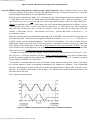
corresponding to +32767 to -32768 counts. For example to output the commanded position
for a sine sweep of
amplitude 2000 counts you should choose the scale factor to
be 0.061 (2000/32767=0.061) This gives close to full +/- 10
volt reading on the
analog outputs. In contrast, if the
numerical value of an item is greater than +/- 32767 counts, for
full scale
reading, you must choose a scale factor of greater than one. Note that the above items are always in counts
(not degrees or radians) within the real time controller and since the DAC's
are 16-bit wide, + 32767 counts corresponds
to +9.999 volts, and -32768 counts
corresponds to -10 volts. gyroscope_Model750_User_Manual.htm[9/28/2015 2:33:52 PM]