1
3,946,220
13
14
printing operation lasts approximately 0.525 millisec
The keyboard is covered with three layers of plastic
onds.
sheeting (not shown) so as to present a smooth wear
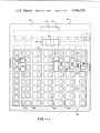
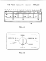
As shown in FIG. 9, the lighting displays used in the
surface to the operator. A clear plastic sheet forms the
bottom layer and an intermediate plastic menu sheet is
positioned over this. The intermediate menu sheet 39 is
preferred embodiment of the invention consist of seven
separate incandescent strips, or bars 54, which can be
a translucent white with clear window portions 40 posi
tioned over the display devices 52. Printed legends for
the identi?cation of the various keys are carried by the
There is also a dot S6 at the bottom of the device which
is used to indicate a number greater than 9. For exam
selectively lighted to form the numerals 0 through 9.
ple, the dot 56 is lighted with the strips or bars 54
de?ning the numeral 1 whenever the numeral II is
intended. Any or all of the eight display elements may
be selectively lighted to thereby form a visual display of
menu sheet. Yellow circles 50 are also placed on the
menu sheet. These circles overlie the snap-action
switches and serve to locate for the operator the opera
ble switch portion of each key. A top sheet of a clear,
tough plastic is provided over the menu sheet to take
the wear from the operator’s use of the keyboard.
any desired numeral up to 15. The strips or bars 54 may
also be selectively lighted to form certain letters.
The keys and their associated display devices are
The keyboard assembly is secured to a closure plate
98 for the bottom of the terminal housing 22. The
closure plate is arranged so as to permit the keyboard
assembly to be dropped a short distance downwardly
away from the housing to permit the changing or re
placement of the protective covering sheets of plastic.
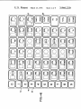
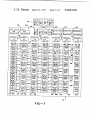
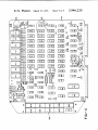
identi?ed and located for the computer by means of
three sets of letter coordinates (see FIG. 7). Each of
the keys has an X coordinate and a Z coordinate. There
are 16 X coordinates starting with X0 and ending with
20
X,,,. There are 4 Z coordinates, Z, through Z4. For the
INTERROGATION OF THE KEYBOARD
display devices, there are 16 X coordinates and 3 Y
coordinates. Each Y coordinate is further divided into
TERMINALS AND COMPUTER OPERATION OF
THE ASSOCIATED DISPLAY DEVICES
eight separate segments identi?ed by the letters a, b, c,
banks are programmed to handle several uses on an
individual display devices 52.
Scanning of the keys of a keyboard and the lighting of
the associated display devices is initiated by an output
d, e, f, g, and t. These letter segments are keyed to the
The central processor unit and its associated memory 25 seven incandescent strips 54 and dot 56 making up the
allocation basis. Allocation is accomplished in a man
ner which permits the simultaneous use of two key
signal from the computer to the keyboard. The com
puter output signal carries 32 bits of data which serve
boards and a printer without any noticeable delay in
the functioning of the individual units being served.
Thus, the central processor unit and memory banks
to interrogate the keyboard and to designate which
function to sense key actuations on both keyboards,
display devices are to be lighted. The ?rst 24 data bits
light all display devices as required, operate the printer
and perform all calculations and other logic sequences
are used to carry the instructions designating the Y
called for by the keyboard operators and/or store man
ager, without causing any noticeable delays at the
printer or either keyboard.
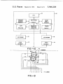
To accomplish this, the computer is programmed to
service the keyboards and the printer on a time-sharing
basis. Because of the necessity of servicing the key
boards and printer separately, the operation of the
computer consists in continuous repetitions of the
cycle shown in FIG. 3. That cycle consists of a ?rst
scanning sequence 100 having two phases; a ?rst phase
in which the keys and display devices of keyboard 1 are
scanned, and a second phase in which the keys and
display devices of keyboard 2 are scanned. After the
scanning sequence 100 is completed the computer next
carries out a processing step 102 in which various logic
sequences for keyboard 1 are done as required. The
processing step 102 is followed by a second scanning
sequence 104 just like the ?rst in which the keys and
display devices of keyboard 1 are scanned and then the
keys and display devices of keyboard 2 are scanned.
coordinates and the letter segments of the display de
35 vices that are to be lighted. The next four data bits
(through the use of a 4 to l6 decoder) designate one of
the 16 X coordinates. This designated X coordinate
then serves to identify the keys being interrogated by
the computer on each output signal as well as the par
ticular display devices to be lighted in response to pre
viously sensed key actuations. The ?nal four data bits
of the output signal are blank so that the keyboard may
impress upon these data positions the Z coordinate of
any key being actuated by the keyboard operator.
45
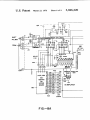
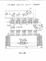
From the computer, the output signal passes in steps
through seven TTL shift registers 112 (FIGS. 8A and
8B) and is then returned to the computer. The ?rst 8
data bits, or byte, will carry the Y, coordinates for
those display devices identi?ed by a Y, coordinate. If
no Y, display devices are to be lighted all 8 data bits
will have a zero voltage. Since a positive voltage is
required to designate a particular display device, 8
blank data bits will pass through the shift registers I12
and return to the computer without turning on any
This second scanning sequence is then followed by a 55 display devices.
second processing step 106 in which logic sequences
If one or more of the ?rst 8 data bits have been im—
for keyboard 2 are performed. A third scanning se
pressed with a positive voltage, that voltage will serve
quence 108 follows and, again, the keys and display
as an instruction that a display device having a Y, coor
dinate is to be lighted. Which Y, display device is to be
step of the cycle, the computer executes a printing 60 lighted will not be known until the X coordinate is also
identi?ed. The X coordinate will be identi?ed by the
operation 110 in which any demands for the printer are
?rst 4 bits of the last 8 bit byte of the computer output
satis?ed. At the end of the printing operation, the com
signal. At the time the Y, coordinate instruction is
puter starts on a repetition of the cycle by initiating
devices of the two keyboards are scanned. In the ?nal
another scanning sequence 100. A complete cycle of
given to the keyboard, the particular letter segments
operations is made 213 times a second. One scanning 65 required to light the necessary strips or dot of the desig
nated display device are also given.
sequence and the following process or printing step
The second 8 data bits, or byte, of the computer
occurs 640 times a second. A scanning sequence lasts
output signal carries the designating instruction for all
approximately 0.975 milliseconds and a processing or