1
MSC 83/28/Add.2
ANNEX 13
Page 15
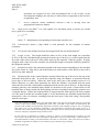
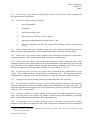
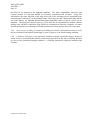
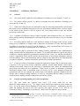
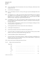
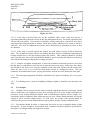
2.3.4 The angle of roll (ϕ1)8 referred to in 2.3.1.2 shall be calculated as follows:
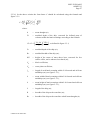
ϕ1 = 109 ∗ k ∗ X 1 ∗ X 2 ∗ r ∗ s (degrees)
where:
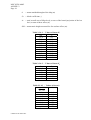
X1 = factor as shown in table 2.3.4-1
X2 = factor as shown in table 2.3.4-2
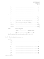
k
r
= factor as follows:
k
= 1.0 for round-bilged ship having no bilge or bar keels
k
= 0.7 for a ship having sharp bilges
k
= as shown in table 2.3.4-3 for a ship having bilge keels, a bar keel
or both
= 0.73 + 0.6 OG/d
with:
OG = KG – d
d
s
= mean moulded draught of the ship (m)
= factor as shown in table 2.3.4-4, where T is the ship roll natural period.
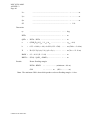
In absence of sufficient information, the following approximate formula
can be used:
Rolling period
T=
2*C * B
GM
( s)
where:
C = 0.373 + 0.023(B/d) - 0.043(Lwl/100).
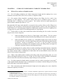
The symbols in tables 2.3.4-1, 2.3.4-2, 2.3.4-3 and 2.3.4-4 and the formula for the
rolling period are defined as follows:
Lwl = length of the ship at waterline (m)
B
8
= moulded breadth of the ship (m)
The angle of roll for ships with anti-rolling devices should be determined without taking into account the
operation of these devices unless the Administration is satisfied with the proof that the devices are effective
even with sudden shutdown of their supplied power.
I:\MSC\83\28-Add-2.doc