1
Circuit Continuity Test
Note!
The tested circuit may be live.
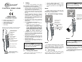
Connect both probes to the tested circuit. An
audible signal and activated LED Ω
indicates
that the circuit is continuous (R<400kΩ).
Note:
Voltage polarization on L2 probe is positive.
2.6
Phase Sequence Test
L1
L1
L3
N
Illumination of Measurement
Point
P-1 can provide illumination of the area
around the point being measured. This is important in locations with poor light (e.g. in distribution
substations). To turn on illumination press the but.
ton marked
3
Battery Replacement
The device is powered from two AAA 1.5V
batteries. Absence of an audible signal after short
circuiting of probes or weak illumination after
pressing the button
is an indication that the
batteries need to be replaced. To do it follow the
procedure below:
Connect probe L1 to
assumed phase L1
and probe L2 to assumed
phase L2. Press the touch
electrode.
L2
PE
2.7
+
L2
The voltage is shown
on the LED indicator.
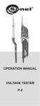
P-1
2.5
690
400
230
120
LED R turned on
indicates in-phase
rotation.
RL
50
24
12
V
+
OPEN
LED L turned on
indicates out of phase
rotation .
4
CLOSE
Cleaning and Maintenance
P-1
After swapping the probes
the opposite arrow should
turn on.
- Disconnect both probes
from the tested circuit.
- Using a tool or a coin
unscrew the battery container
by a counter clickwise
movement and remove it.
- Replace the battery paying
attention to correct polarization.
- Insert the container rotating
it clockwise.
NOTE!
Use only maintenance methods that the manufacturer specified in this instruction.
The device can be cleaned using a soft, damp
cloth using generally accessible detergents. Do
not use any solvents or cleaning agents that could
scratch device’s housing (polishing powders,
creams etc.).
Notes:
Phase sequence can be tested only in a 3
phase installation.
Electronic circuitry is maintenance free.
5
Storage
When storing the device you need to comply
with the following guidelines:
• Replace protective caps on the probes,
• Make sure that the device is dry,
•
Decommissioned electrical equipment should
be sent to an appropriate waste depot in compliance with legal acts governing electronic waste
management..
s) Frequency range for bipolar phase rotation indicator: 50…60Hz
t) Power supply: 2x1.5V AAA/LR03
u) Dimensions: ok. 240x60x30 mm
v) Weight with batteries: ok. 0,2kg
w) Working temperature: -10..+55°C
x) Storage temperature: -30°C..+70°C
y) Quality standards: design and manufacturing
ISO 9001 compliant
z) the product meets the EMC requirements
(immunity for industrial environment) according to the following standards EN 613261:2006 and EN 61326-2-2:2006
Do not disassemble the equipment before
sending it to a waste depot.
8
Follow local legislation regulating disposal of
packaging and batteries.
The manufacturer of the device and a provider of warranty and post-warranty services is:
6
If the device is to be stored for a prolonged
period of time, remove the batteries.
Decommissioning and Recycling
Decommissioned electrical equipment should
be stored separately from other type of waste.
7
Technical Specifications
a) Type of insulation: double, EN 61010-1 compliant
b) Safety category: III 1000V (IV 600V) as per
EN 61010-1
c) Housing degree of protection as per EN
60529: IP65
d) Voltage range: 12…690V AC/DC
e) Voltage indications: 12V, 24V, 50V, 120V,
230V, 400V, 690V
f) input resistance
Uin
12V, 24V, 50V
120V
230V
400V
690V
Rin
~ 6kΩ
~ 20kΩ
~ 70kΩ
~ 150kΩ
~ 240kΩ
g) Accuracy of voltage indications: as per EN
61243-3
h) Voltage frequency range: 0…400Hz
i) Maximum current: IS<0,2A/IS(5s)<3,5mA
j) Maximum work interval: 30s
k) Minimum recovery time after being connected
for 30s: 240s
l) Minimum voltage triggering the device: <12V
m) Voltage range for unipolar phase indicator:
50…690V
n) Frequency range for unipolar phase indicator:
50…400Hz
o) Continuity test range: 0…400kΩ
p) Continuity test accuracy: ±50%
q) Continuity test current: 3µA
r) Voltage range for bipolar phase rotation indicator: 100…690V
Manufacturer
SONEL S. A.
ul. Wokulskiego 11
58-100 Świdnica
tel. (0-74) 858 38 60
(0-74) 858 38 00
fax (0-74) 858 38 08
e-mail: export@sonel.pl
internet: www.sonel.pl
Note:
The manufacturer is the only service provider
authorized to provide repair the device.
Note:
The manufacturer reserves the right to introduce changes to device’s look, accessories
and specifications.
Version 1.7 23.02.2011