1
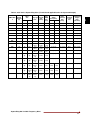
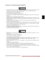
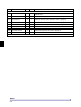
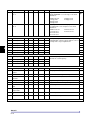
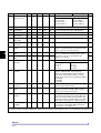
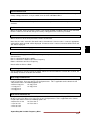
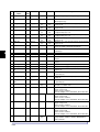
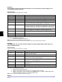
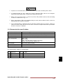
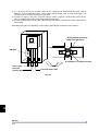
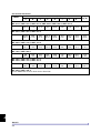
3. The feedback at J10 in PCA-2004A is missing.
Ensure correct wiring of PCA-2004A
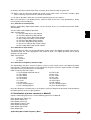
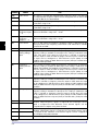
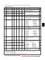
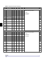
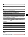
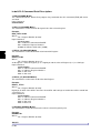
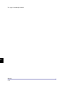
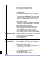
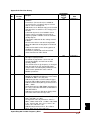
20 Input Phase Sequence
Fault *
1. Check the phase sequence of the mains power supply, if the phase
sequence is reverse, change any two phases.
21 Driver Fault
1. The fault may be from Driver Board side.
Switch off the power supply and remove the FRC in case of wire
interface. Check the cable on both the sides for proper crimping.
Insert the cable properly and check again. If the fault persists,
proceed for the next step.
In case of fiber optic interface, remove all the fiber optic cables,
check them and insert them again properly. Check again. If the fault
persists, proceed for the next test.
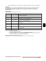
2. IGBT Gate Driver board may have problem.
Replace the IGBT Gate Driver board and check again. Take antistatic precautions while changing the board.
3. Check the SMPS supply voltage.
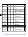
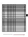
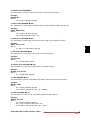
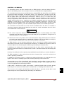
22 Speed Deviation Fault
1. Check the encoder wiring.
2. Check the proper earthing of encoder.
3. Problem in auto tuning parameter. Enter the correct motor
parameter and repeat the procedure for auto tuning.
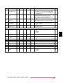
23 Over Speed Fault
1. Check the encoder wiring.
2. Check the proper earthing of encoder.
3. Problem in auto tuning parameter. Enter the correct motor
parameter and repeat the procedure for auto tuning.
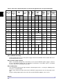
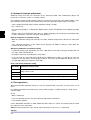
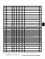
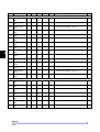
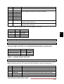
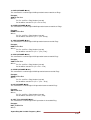
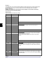
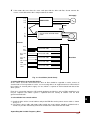
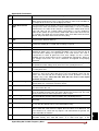
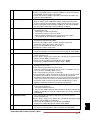
24 IU-2 Temperature Fault**
25
26
27
28
29
1. A trouble may have occurred in the cooling blower of respective
Inverter or diode unit in case of parallel inverter.
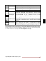
IU-3 Temperature Fault**
Replace it if necessary.
IU-4 Temperature Fault** 2. The ambient temperature may have risen.
Lower the ambient temperature (less than 50 °C for 400V series or
IU-5 Temperature Fault**
less than 40 °C for 500V / 600V series).
DU-1 Temperature Fault** 3. The carrier frequency may be set too high.
DU-2 Temperature Fault** 4. The thermistor is not connected or loosely connected at J16 of
PCA-2014A and TB1 of PCA-2013A respectively. Disconnect the
thermistor and ensure that the thermistor shows resistance greater
then 2.2kohm but less then 60kohm. Reconnect thermistor properly.
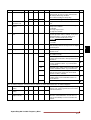
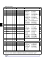
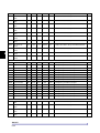
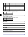
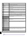
30 IU-1 Current Sensor Fail** 1. Loose connection of hall current sensor cable connected at J11 to
J15 of PCA-2013A. Switch off the unit and remove the cable. Check
31 IU-2 Current Sensor Fail**
for proper crimping of cable on both sides. If found abnormal,
32 IU-3 Current Sensor Fail**
replace the cable and check again.
33 IU-4 Current Sensor Fail** 2. One or more current sensor has failed.
Remove connector J11 to J15 and reset the fault. If the fault can be
34 IU-5 Current Sensor Fail**
reset, find out which current sensor has failed.
3. If after removing connector J11 to J15, the problem persists,
replace PCA- 2013A.
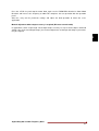
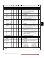
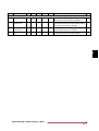
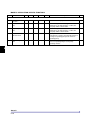
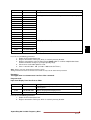
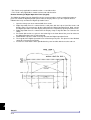
35 IU-1 I-Unbalance Fault**
36 IU-2 I-Unbalance Fault**
37 IU-3 I-Unbalance Fault**
38 IU-4 I-Unbalance Fault**
39 IU-5 I-Unbalance Fault**
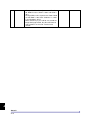
1. Check whether the sensors are connected properly or not. If the
sensor of one or more Inverter Unit is not connected, this fault may
come.
2. There may be problem with the driver board or fiber optic cable.
Check the driver board and fiber optic connections. If required
replace it.
3. There may be loose connection of the fiber optic cable or problem
with the Fiber Optic Interface Board PCA-96A. Checks the
connection with of the fiber optic cables are if required change the
PCA-96A.
4. Check the current sensor connections at Driver Interface Board
PCA-2013A. If required, change the board.
Axpert-Eazy AC Variable Frequency Drive
A.13
13
A