1
When operating in voltage mode, the control software generates a fixed with PWM signal onto iRef
which corresponds with the desired current limit. Assuming a 5v supply, a PWM duty cycle of 50% will
generate a current reference of 2.5v. Similarly, a 25% duty cycle generates a limit of 1.25v.
Once the appropriate current limit has been set, the controller generates a variable width PWM signal,
where the width of the signal is proportional to the amount of power to be delivered to the motor. Due to
the load on the system, and the gains in the compensator, it is possible that the controller will generate a
PWM signal that would cause the motor to draw current in excess of the programmed current limit.
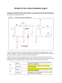
In this scenario, the comparator (shown above) ensures that this doesn’t happen. As the PWM to the
motor increases, so does the ‘current feedback’ running into the top of the comparator. When the
feedback voltage exceeds the programmed limit, the ETR pin is activated, and the PWM signals are
immediately deactivated.
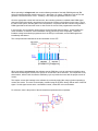
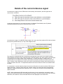
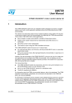
This concept was also illustrated in the documentation for the ST7:
When operating in current mode, the software sets the PWM duty cycle to maximum permissible value,
and varies the iRef signal, based on the amount of current that is to be delivered. The comparator circuit,
shown above, will then limit the effective PWM duty cycle to provide the motor with the proper amount of
current.
This implies ‘current limit’ settings in the software do not directly apply [after ramp-up] when operating in
current drive mode. The value on the display, modified using the joystick, directly affects value of the iRef
signal. So this signal serves as the ‘commanded current’, rather than a current limitation.
For reference, here is the portion of the schematic that implements this comparator.