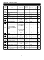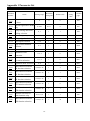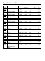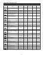
1
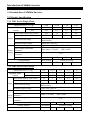
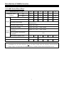
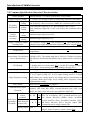
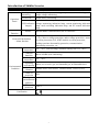
Introduction of Shihlin Inverter
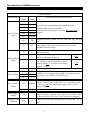
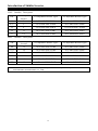
Introduction of Inverter
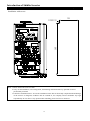
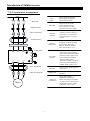
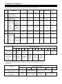
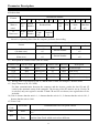
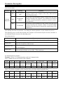
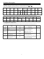
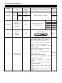
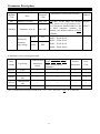
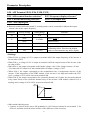
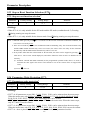
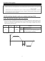
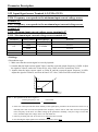
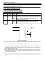
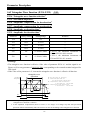
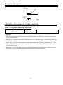
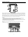
Note: 1. For multi-function control terminals, please refer to P.80~P.84, P.86, and for multi-function output
terminals, please refer to P.40 in Chapter 5.
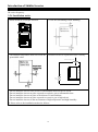
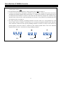
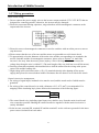
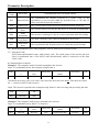
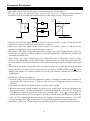
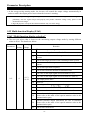
2. For SS2-TYPE series inverters, the multi-function control terminals have both the sink input mode and
the source input mode. There is a jumper that can be used to alternate between those two modes. If the
jumper is on the left side, the sink input mode is chosen, while the source input mode is chosen if the
jumper is on the right side. Shown as follows:
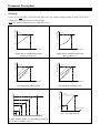
Sink Input
Source Input
No matter what kind of multi-function control terminal is used, all of its outside wire arrangement can
be considered as a simple switch. If the switch is ‘on’, the control signal will be put into the terminal. If
the switch is ‘off’; the control signal is shut off.
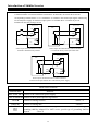
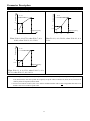
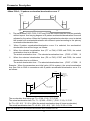
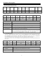
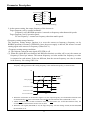
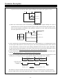
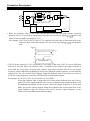
If the sink input mode is selected, the function of the terminal is active when it is shorted with SD or
connected to the external PLC. At this mode, the current flows out of the corresponding terminal when
it is ‘on’. Terminal SD is common the contact input signals. When using an external power supply for
transistor, please use terminal PC as a common to prevent malfunction caused by leakage current.
Inverter
Inverter
PLC
STF
STF
STR
I
STR
PC
SD
PC
DC
24V
I
Sink Input: the multi-function control
terminal is shorted directly with SD
SD
DC
24V
Sink Input: the multi-function control terminal
is connected directly with open-collector PLC
Inverter
PLC
STF
STR
PC
DC
24V
SD
DC
24V
I
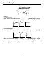
Sink Input: the multi-function control terminal is connected
with open-collector PLC and external power supply
19