1
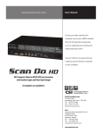
Plus, SCAN DO ULTRA/D – With Serial Digital Video Output USER’S MANUAL WORLD HEADQUARTERS 55 Cabot Court Hauppauge, N.Y. 11788 USA Tel: (631) 273-0404 Fax: (631) 273-1638 www.commspecial.com Email: info@commspecial.com Communications Specialties Pte Ltd 100 Beach Road #22-09 Shaw Tower Singapore 189702 Tel: +65 6391 8790 Fax: +65 6396 0138 Email: csiasia@commspecial.com Copyright 2001 Part #: 120530 Rev.E Scan Do Ultra User’s Manual Scan Do Ultra User’s Manual CONTENTS User & Certification Information ................................................ 3 Introduction .................................................................................. 5 Installation .................................................................................... 6 Front Panel Menu ........................................................................ 8 Operation ..................................................................................... 9 Upgrading the Firmware ............................................................ 24 Accessories ............................................................................... 25 Rear Connector Pin-outs ........................................................... 26 Statement of Warranty .............................................................. 27 INCLUDED WITH THIS PRODUCT 1 - Scan Do Ultra computer to video scan/down converter 1 - AC power line cord 1 - 6 foot computer input cable for VGA and Macintosh ® 1 - 12 foot composite video output cable 1 - 12 foot S-Video output cable 1 - 6 foot RS-232 serial data cable 1 - Rack mounting kit 1 - Set of spare feet and a spare fuse 1 - User’s Manual 1 - Remote Control Operation Manual 1 - Product Registration card AVAILABLE OPTIONAL ACCESSORIES • 6 foot 13W3 male to BNC cable for workstation input • 6 foot 13W3 female to BNC cable for workstation monitors • 12 foot BNC adapter cable for RGB input or output • 12 foot Sharp projector cable for RGB output • 12 foot SCART cable for output • RF modulator for North America channels 3 and 4 • AC line cord for North America, Japan, UK, Australia, or Continental Europe See page 24 for a complete list of products and part numbers. Scan Do is a registered trademark of Communications Specialties, Inc. Macintosh and Mac are registered trademarks of Apple Computer, Inc. Page 28 Scan Do Ultra User’s Manual Scan Do Ultra User’s Manual Page 1 STATEMENT OF WARRANTY C WARNING: TO REDUCE THE RISK OF FIRE OR ELECTRONIC SHOCK, DO NOT EXPOSE. THIS APPLIANCETO RAIN OR MOISTURE. CAUTION: TO REDUCE THE RISK OF CAUTION RISK OF ELECTRIC SHOCK DO NOT OPEN ELECTRONIC SHOCK, DO NOT REMOVE COVER. NO USER SERVICEABLE PARTS INSIDE. REFER SERVICING TO QUALIFIED SERVICE PERSONNEL. ommunications Specialties, Inc. (CSI) warrants that for a period of three years after purchase by the Buyer, Scan Do Ultra will be free from defects in material and workmanship under normal use and service. A Return Material Authorization (RMA) number must be obtained from CSI before any equipment is returned by the Buyer. All material must be shipped to CSI at the expense and risk of the Buyer. CSI’s obligation under this warranty will be limited, at its option, to either the repair or replacement of defective units, including free materials and labor. In no event shall CSI be responsible for any incidental or consequential damages or loss of profits or goodwill. CSI shall not be obligated to replace or repair equipment that has been damaged by fire, war, acts of God, or similar causes, or equipment that has been serviced by unauthorized personnel, altered, improperly installed or abused. RMA numbers and repairs can be obtained from: This symbol warns the user of uninsulated voltage within the unit that can cause dangerous electronic shocks. This symbol alerts the user that there are important operating and maintenance instructions in the literature accompanying this unit. Communications Specialties, Inc. 55 Cabot Court Hauppauge, NY 11788 USA TEL: (631) 273-0404 FAX: (631) 273-1638 or, in the Asia Pacific Region: Communications Specialties Pte Ltd Singapore TEL: +65 6391 8790 FAX: +65 6396 0138 (See page 5 of this manual for complete address) RMA numbers can also be obtained from our web site: http://www.commspecial.com Please have your serial number (located underneath your unit) available when contacting us. Page 2 Scan Do Ultra User’s Manual Scan Do Ultra User’s Manual Page 27 REAR CONNECTOR PIN-OUTS POWER USER & CERTIFICATION INFORMATION AC Line VGA OUT/MAC IN (HD-15 CONNECTOR) FCC STATEMENT 1 2 3 4 5 6 7 8 9 10 11 12 13 14 15 VGA Out Red Green Blue ID bit 2 Ground Red Ground Green Ground Blue Ground N/C Monitor Present Ground (ID bit 0) ID bit 1 H-Sync Out V-Sync Out ID bit 3 MAC In Red Green Blue ID bit-2 Ground Red Ground Green Ground Blue Ground N/C Computer Present Ground (ID bit 0) ID bit 1 H-Sync In V-Sync In Comp. Sync In 1 2 3 4 5 6 7 8 9 10 11 12 13 14 15 VGA In Ground Red Reserved ID bit 0 Green Red Ground ID bit 1 N/C Blue ID bit 2 Ground V-Sync In Computer Present Ground H-Sync In MAC Out Ground Red Comp. Sync Out ID bit 0 Green Red Ground ID bit 1 N/C Blue ID bit 2 Ground V-Sync Out Monitor Present Ground H-Sync Out SDI, COMPONENT VIDEO, VIDEO, GENLOCK IN/OUT, AND RGBHV INPUT (BNC) Center Outer Video Out Video Ground S-VIDEO OUTPUT 1 2 Ground Ground RS-232 REMOTE CONTROL 1 2 3 4 DCD RXD TXD DTR VGA IN/MAC OUT (DB-15 CONNECTOR) Page 26 Scan Do Ultra User’s Manual WARNING: This equipment generates, uses and can radiate radio frequency energy and if not installed and used in accordance with the instruction manual, may cause interference to radio communications. It has been tested and found to comply with the limits for a Class A computing device pursuant to Subpart B of Part 15 of FCC Rules, which are designed to provide reasonable protection against such interference when operated in a commercial environment. Operation of this equipment in a residential area is likely to cause interference in which case the user, at his own expense, will be required to take whatever measures may be required to correct the interference. UL INFORMATION This product carries the UL and CUL marks for ITE equipment, Listing #: 8D47 CE INFORMATION Standards to which conformity is declared: EMC: EN 55022: 1994, CISPR 22: 1993, Class B Limit EN 50082-1: 1992 IEC 801-2: 1991 IEC 801-3: 1984 IEC 801-4: 1988 Low Voltage Directive: EN 60950: 1992+A1+A2 IEC 950: 1991+A1+A2 3 Luminance 4 Chrominance 5 6 7 8 Ground DSR RTS CTS 9 No Connection Scan Do Ultra User’s Manual Page 3 INTRODUCTION UPGRADING THE FIRMWARE F rom time to time, CSI upgrades product firmware to fix bugs and upgrade features. The firmware inside Scan Do Ultra is designed to be upgraded by you or your dealer in the field. However, if you prefer, you have the option of returning the unit to us and we will be happy to perform the upgrade for you. For the latest revision of the firmware, call us or consult our World Wide Web site at: WWW.COMMSPECIAL.COM You may obtain a firmware upgrade either by downloading it from our Web site or by requesting a distribution disk from Communications Specialties. To find out what the present revision of the firmware in your product is, go to the STATUS SELECTION Submenu and select VERSION. To upgrade the version of your firmware: • Power Off Scan Do Ultra • Connect the RS-232 Serial cable provided from the RS-232 port on the back of Scan Do Ultra to a serial port on your computer. NOTE: The cable provided is a straight-through cable designed to connect directly to a 9-pin serial port on a PC. • Power On Scan Do Ultra • Set the BAUD rate of Scan Do Ultra and your computer to 9600 baud. • Run the upgrade software provided on disk or down loaded from our Web site. • Follow the instructions when you run the software. Communications Specialties, Inc. 55 Cabot Court Hauppauge, NY 11788 USA TEL: (631) 273-0404 FAX: (631) 273-1638 WWW: http://www.commspecial.com EMAIL: info@commspecial.com Communications Specialties Pte Ltd 100 Beach Road #22-09 Shaw Tower Singapore 189702 TEL: +65 6391 8707 FAX: +65 6396 0138 WWW: www.commspecial.com EMAIL: csiasia@commspecial.com T hank you for purchasing Scan Do Ultra, Communications Specialties’ broadcast-quality scan converter and down converter. With Scan Do Ultra, you now have the ability to convert high-resolution computer and workstation graphics into a form suitable for integration within a traditional video (NTSC or PAL) environment. Applications include broadcasting, video production and editing, presentation display, videoconferencing and multimedia development. In addition, Scan Do Ultra/D provides the ability to output the converted computer video in serial digital format, according to SMPTE 259M standards, so as to interface with all digital video production, editing and graphics equipment. Scan Do Ultra does not require any special software and operates completely externally from your computer. Scan Do Ultra performs as both a scan converter and down converter, meaning that it can convert computer video not only to standard, interlaced television video, but also to lower resolutions of noninterlaced computer video. When operating as a scan converter, Scan Do Ultra can convert any non-interlaced computer video input with a horizontal sync frequency from 24 to 90 kHz to a broadcast quality NTSC or PAL video. Four video output formats are provided -composite, S-Video, RGBS, or YUV. In addition, Scan Do Ultra/D also offers standard SMPTE 259M digital output. When functioning as a downconverter, Scan Do Ultra can take the same range of computer resolutions and convert them to either 640 x 480 VGA/Mac or 800 x 600 SVGA. Like all the products from Communications Specialties, Scan Do Ultra comes with our continuing commitment to provide support. In order to assist us in this process, please be sure to mail in your product registration card. This will make it easier for us to notify you with any new product announcements or other information concerning our product line. Should you need to contact us for support, our office is open Monday through Friday, from 8:30 AM to 5:00 PM Eastern Time. We also offer a comprehensive web site for your added convenience. Thank you for choosing Scan Do Ultra. As always, we welcome your comments and suggestions. Page 24 Scan Do Ultra User’s Manual Scan Do Ultra User’s Manual Page 5 INSTALLATION 1. Disconnect your monitor from the monitor port on your computer. 2. For a VGA or Mac computer, use the provided 6-foot input cable to connect the monitor port on your computer to the connector on the rear panel of Scan Do Ultra (either VGA In or MAC IN). This reversible cable is used for both VGA and Mac computers. 3. 4. As an alternative, you may use the 5 BNC connectors to connect RGB and sync signals. You may connect computer video with either separate sync (H and V), composite sync (CS), or RGB with sync on GREEN. Scan Do Ultra will automatically determine which sync format you are using. Connect your monitor, if you have one, to the MONITOR connector labeled VGA OUT or MAC OUT or, if you are using the BNC input connectors, to the BNC COMPUTER LOOPTHROUGH connectors. 5. Connect the AC power cord provided with Scan Do Ultra to the AC inlet connector. Connect the AC line cord to the wall outlet to provide power to Scan Do Ultra. 6. Connect one of Scan Do Ultra's NTSC/PAL video outputs to your video equipment. STATUS DISPLAY (from the Status Selections menu) The STATUS DISPLAY: • Shows a collection of input and output states for the unit in real time • No soft button choices are active Source Line xx xx H-kHz V-Hz xx xx Lock Format BNC xx xx xx SOURCE: Shows whether the 15-pin VGA/Mac connectors or the BNC connectors are the active input. LINE: Shows how many total horizontal scan lines per frame there are in the computer signal at the active input. This includes both active and blanking lines. H-kHz: Shows what the approximate horizontal sync frequency is of the active input. V-Hz: Shows what the approximate vertical sync frequency is of the active input. LOCK: Shows whether genlock is on or off when in the NTSC or PAL output format modes. FORMAT: Shows what the active output format is: NTSC, PAL, VGA640, VGA800 or MAC640 NTSC/PAL OUTPUTS COMPOSITE: This is a single composite video signal. S-VIDEO: This is an advanced form of video where the brightness and color parts of the image are actually on two separate signals. BNC: Shows the active format of the output component BNC connectors on the rear panel. The format may be either RGB, RGsB, Betacam or MII. RED, GREEN, BLUE, SYNC: This output has separate RED, GREEN, BLUE, and SYNC signals which can be used by some video equipment and monitors. Composite sync can be added to the GREEN signal. See Page 15 for details. Y, R-Y, B-Y: This component output format uses the same output connectors as RED, GREEN, and BLUE. The front panel selection (see Page 15 for details) determines whether these connectors are RGB or Component outputs. SDI: (Scan Do Ultra/D only) This output is compliant with SMPTE 259M and provides a serial digital component output. Page 6 Scan Do Ultra User’s Manual Scan Do Ultra User’s Manual Page 23 STATUS SELECTIONS MENU (from the Main menu) The STATUS SELECTIONS menu: • Allows for resetting the system • Indicates firmware versions • Displays system status STATUS SELECTIONS ... RESET VERSION STATUS RESET SUBMENUS (from the Status Selections menu) DOWN CONVERTED COMPUTER COMPATIBLE OUTPUTS DISPLAY RESET: Initiates a reset of the system. This will erase all saved sizing and control settings in the five preset locations and will restore all processing controls to their factory default settings. VERSION: Displays the versions of firmware and downloadable test patterns in use by the system. DISPLAY: Continually displays system status information about which input has been selected, the output and component formats and the characteristics of the input signal. In addition to the NTSC/PAL outputs just described, Scan Do Ultra features three down converted outputs that provide RGB video with sync signals that correspond to popular computer video timings. These outputs can be used directly with computer monitors, data projectors, and LCD panels to achieve higher resolutions than possible with the NTSC/PAL outputs. The front control panel allows you to designate which of the three outputs is active (see page 13). The three down converted outputs on Scan Do Ultra are described below: RED, GREEN, BLUE, SYNC: This output is active in all three output modes: VGA640, VGA800, and MAC. Sync can be added to the GREEN signal. See Page 15 for details. VGA: This output is active when the VGA640 and VGA800 modes are selected. The pinout is compatible with to a standard VGA monitor. MAC: This output is active when the MAC mode is selected. The pinout is compatible with a standard MAC monitor. The STATUS RESET submenus: • Are two menus for resetting the system to its defaults STATUS RESET TO DEFAULT SETTINGS? CANCEL YES These down converted outputs can be set for one of three different resolutions and timing standards (or Formats): • VGA640: 640 x 480 @ H=31.5 kHz, V=60 Hz • VGA800: 800 x 600 @ H=35.1 kHz, V=56 Hz • MAC: 640 x 480 @ H=35.0 kHz, V=66 Hz STATUS RESET CONFIRMATION: ARE YOU SURE? YES CANCEL STATUS VERSION SUBMENU (from the Status Selections menu) The STATUS VERSION submenu: • Displays the version number of the Base and Option firmware in the product • Displays the version of the downloadable Test Pattern in the product These version numbers are useful when diagnosing problems. STATUS VERSION ... BASE OPTION Page 22 Scan Do Ultra User’s Manual TEST-PAT Scan Do Ultra User’s Manual Page 7 FRONT PANEL MENU The following tree shows the overall menu structure for Scan Do Ultra. Details of each SubMenu are given on the page number indicated. VIEW ZOOM CONTROL SUBMENU (from the View Selections menu) The VIEW ZOOM control menu: • VIEW ZOOM? 100% - Page 9 MAIN MENU INPUT SELECTION Page 10 Page 12 Pressing the ZOOM soft button will toggle you to the SIZE and MOVE control menus. Page 16 PROCESS SELECTION VIEW SIZE CONTROL SUBMENU (from the View Selections menu) The VIEW SIZE control menu: • Page 22 STATUS SELECTION SOURCE (Page 10) FORMAT (Page 13) VID/S-VID (Page 16) SAVE (Page 20) RESET (Page 22) GENLOCK (Page 11) FLICKER (Page 13) COMPONENT (Page 18) RECALL (Page 20) VERSION (Page 22) ZOOM (Page 21) DISPLAY (Page 23) HANDSHAKE (Page 12) + The - soft button will shrink the image. Page 20 VIEW SELECTION BAUD (Page 12) ZOOM The + soft button will expand the image. OUTPUT SELECTION PHASING (Page 11) Proportionally changes the horizontal and vertical size at the same time THRESHOLD (Page 14) LEVEL (Page 13) COMPONENT (Page 15) SIZE (Page 21) MOVE (Page 21) TEST-PAT (Page 15) Independently changes the horizontal and vertical size VIEW SIZE? HH+ SIZE V- V+ The H+ soft button will expand the image horizontally. The H- soft button will shrink the image horizontally. The V+ soft button will expand the image vertically. The V- soft button will shrink the image vertically. Pressing the SIZE soft button will toggle you to the MOVE and ZOOM control menus. VIEW MOVE CONTROL SUBMENU (from the View Selections menu) The VIEW MOVE control menu: • Independently changes the horizontal and vertical position The H+ soft button will move the image to the right. VIEW MOVE? HH+ MOVE V- V+ The H- soft button will move the image to the left. The V+ soft button will move the image down. The V- soft button will move the image up. Pressing the MOVE soft button will toggle you to the ZOOM and SIZE control menus. Page 8 Scan Do Ultra User’s Manual Scan Do Ultra User’s Manual Page 21 OPERATION VIEW SELECTIONS MENU (from the Main menu) S The VIEW SELECTIONS menu accesses: • Five memory locations • Image Zoom function • Image Size function • Image Move Function VIEW SELECTIONS ... SAVE RECALL ZOOM SAVE: can Do Ultra is designed to be easy to use, and you should find its operation to be intuitive. However, we suggest that you read the following pages to fully understand how Scan Do Ultra operates and to take advantage of its many features. SIZE The center of operational control for Scan Do Ultra is the front panel LCD display, the five “soft” buttons directly below the display, and the MENU BACK button to the right of the display. All of the functions and selections of Scan Do Ultra are accessed through these buttons and displayed on the LCD. The functions are grouped in a “tree” structure. The top row of the LCD display will describe the group of functions available. The bottom row will give up to five specific functions that the user can select by pressing the corresponding soft button directly below. MOVE Saves the current settings for image size, screen position (move), and process controls in one of five locations RECALL: Restores the saved setting from one of five locations VIEW SAVE SUBMENU (from the View Selections menu) Enlarges or shrinks the displayed image by ganging together both H and V sizing. SIZE: Allows independent control of horizontal and vertical image size MOVE: Allows independent horizontal and vertical positioning of the displayed image. The descriptions below are in accordance with the grouping of these functions in the tree structure used. MENU BACK BUTTON The VIEW SAVE submenu: • Has five storage locations • Each location saves image size and position • Each location saves image process control settings VIEW SAVE? 1 VIEW RECALL SUBMENU (from the View Selections menu) Pressing the MENU BACK button will bring you back to the previous menu level or “up” the menu tree. ZOOM: 2 3 4 MAIN MENU The MAIN menu: • Is the top most menu in the tree. • Offers five choices to access the major group of functions MAIN MENU INPUT OUTPUT PROCESS VIEW STATUS 5 INPUT: Accesses the INPUT SELECTIONS submenu To save the current image display and process control settings, press the soft button below the location number. Any previous settings in that location will be erased. OUTPUT: Accesses the OUTPUT SELECTIONS submenu PROCESS: Accesses the PROCESS SELECTIONS submenu The VIEW RECALL submenu: VIEW: Accesses the VIEW SELECTIONS submenu • STATUS: Accesses the STATUS SELECTIONS submenu Recalls and applies to the current image the display and process control settings stored at a location VIEW RECALL? 1 2 3 4 5 To recall the stored image display and process control settings, press the soft button below the desired location number. Page 20 Scan Do Ultra User’s Manual Scan Do Ultra User’s Manual Page 9 INPUT SELECTONS MENU (from the Main menu) PROCESS COMPONENT: BETA/MII SUBMENU (from the Process Selection menu) The INPUT SELECTIONS menu is used to select: • The input source for conversion • RS-232 port Remote Control parameters • Genlock controls and timing set up The PROCESS COMPONENT:RGBS/RGsB submenu: • Makes available controls for Brightness, Contrast and Color saturation • Acts only on the Component output in the Beta and MII modes The INPUT SELECTIONS menu has submenus to access these functions: INPUT SELECTIONS ... SOURCE GENLOCK PHASING BAUD HANDSHAKE SOURCE: Accesses the INPUT SOURCE CONNECTOR menu for selecting the computer source GENLOCK: Accesses the INPUT GENLOCK SIGNAL menu PHASING: Accesses the INPUT GENLOCK PHASING menu BAUD: Acceses the INPUT BAUD RATE menu HANDSHAKE:Accesses the INPUT HANDSHAKE menu Note: The GENLOCK choice will only appear if the NTSC or PAL output formats have been selected. Note: The PHASING choice will only appear if GENLOCK is ON and a valid genlock reference is present. INPUT SOURCE CONNECTOR SUBMENU (from the Input Selections menu) The INPUT SOURCE CONNECTOR submenu selects: • The 15-pin VGA/MAC connector, or • The set of 5 BNC connectors Selecting the choice 15-PIN will convert the signal on either the DB15 connector (VGA IN) or on the HD-15 connector (MAC IN). The alternate connector not used for the input may be used for a loopthrough computer monitor. Selecting the choice BNC will convert the signal on the set of BNC input connectors. This input will automatically detect and process either separate H and V sync, composite sync, or sync-on-green formats. INPUT SOURCE CONNECTOR? 15-PIN Page 10 Scan Do Ultra User’s Manual PROCESS COMPONENT:BETA/MII ... BRIGHT CONTRAST COLOR Press one of the soft buttons under the function you want to control and a second control menu will appear specifically for that function. PROCESS COMPONENT: BETA/MII CONTROL MENUS (from the Process Component:Beta/ MII submenu) The PROCESS COMPONENT:BETA/MII control menus: • Looks the same for the Brightness, Contrast and Color functions PROCESS COMPONENT:BETA/MII BRIGHTNESS? - [ ...............................] + You can switch between control of Brightness, Contrast and Color functions by pressing the MENU BACK button to go back to the PROCESS COMPONENT:BETA/MII submenu and then selecting the soft button for the function to control. BNC Scan Do Ultra User’s Manual Page 19 PROCESS COMPONENT:RGB SUBMENU (from the Process Selection menu) The PROCESS COMPONENT:RGBS/RGsB submenu: • Makes available controls for Brightness, Contrast, and RGB Balance • Acts only on the Component output in the RGB mode INPUT GENLOCK SIGNAL SUBMENU (from the Input Selections menu) Turns the genlocking function on or off If ON is selected, the NTSC/PAL outputs will be locked to the reference signal source on the GENLOCK INPUT connector. Press one of the soft buttons under the function you want to control and a second control menu will appear specifically for that function. If OFF is selected, the NTSC/PAL outputs will not be locked to the genlock reference signal even if present. Instead the timing of the NTSC/PAL outputs will be determined by the internal timing generator. Note: This submenu is available only when NTSC or PAL output modes are selected. The PROCESS COMPONENT:RGB/RGsB control menus: • • INPUT GENLOCK SIGNAL AS REFERENCE? OFF ON PROCESS COMPONENT:RGB/RGsB ... BRIGHT CONTRAST RGB-BALANCE PROCESS COMPONENT:RGB CONTROL MENUS (from the Process Component:RGB submenu) The INPUT GENLOCK SIGNAL submenu: Looks the same for the Brightness and Contrast functions. PROCESS COMPONENT:RGB/RGsB BRIGHTNESS? - [ ...............................] + You can switch between control of Brightness, Contrast, and Color Balance functions by pressing the MENU BACK button to go back to the PROCESS COMPONENT:RGB/RGsB submenu and then selecting the soft button for the function to control. NOTE: Pressing the Middle soft button will reset the function control to the middle (default) of the scale. The RGB BALANCE control menu looks a little different: RGBS/RGsB BALANCE? + +00 RED +00 GREEN +00 BLUE This function is activated by pressing the soft button(s) for thecolor(s) whose level you want to adjust and then pressing the + or - button to increase or decrease the level. The number above the color will change to show you the relative levels between the colors. This function is useful in compensating for variations in the colorimetry of the display monitor. INPUT GENLOCK PHASING SUBMENU (from the Input Selections menu) The INPUT GENLOCK PHASING submenu: • Allows for the adjustment of horizontal and subcarrier timing when genlocking INPUT GENLOCK PHASING? HH+ SC- SC+ Buttons H- and H+ will adjust the relative advance or delay of the video output with respect to the reference horizontal sync. Buttons SC- and SC+ will advance or delay the relative phase of the output subcarrier with respect to the reference burst. NOTE: Proper genlock phasing can ony be achieved with the use of a waveform monitor and vectorscope locked to the genlock reference signal. NOTE: INPUT GENLOCK PHASING submenu will only appear when there is a valid genlock reference signal present. NOTE: All values will be effected up or down by any adjustments you make to the CONTRAST control. Page 18 Scan Do Ultra User’s Manual Scan Do Ultra User’s Manual Page 11 INPUT BAUD RATE SUBMENU (from the Input Selections menu) The INPUT BAUD RATE submenu: • Sets the baud or data rate for the RS-232 Remote Control port PROCESS VID/S-VID:PAL SUBMENU (from the Process Selection menu) The PROCESS VID/S-VID:PALsubmenu: • INPUT BAUD RATE FOR REMOTE CONTROL? OFF 1200 2400 4800 9600 PROCESS VID/S-VID:PAL... BRIGHT CONTRAST COLOR The OFF setting will disable the Remote Control function. The other settings will set the baud rate. This must match your control computer’s baud rate. INPUT HANDSHAKING SUBMENU (from the Input Selections menu) Press one of the soft buttons under the function you want to control and a second control menu will appear specifically for that function. NOTE: COLOR can only be adjusted when the COMPONENT OUTPUT TYPE is selected to either BETA or MII. The INPUT HANDSHAKING submenu: • Makes available control menus for Brightness, Contrast and Color Sets the type of flow control or “handshaking” between Scan Do Ultra and the control computer INPUT HANDSHAKING FOR REMOTE CONTROL? NONE HARD SOFT BOTH Handshaking is necessary to ensure that neither Scan Do Ultra nor the control computer overflow each other’s communications buffer. The type of handshaking selected must match that of the control computer's. OUTPUT SELECTIONS MENU (from the Main menu) The OUTPUT SELECTIONS menu is used to select: • The output format type • The amount of flicker reduction • The component video format type • A test pattern for display OUTPUT SELECTIONS FORMAT FLICKER COMPONENT PROCESS VID/S-VID:PAL CONTROL MENUS (from the Process Vid/S-Vid:PAL submenu) The PROCESS VID/S-VID:PAL control menus: • Looks the same for the Brightness, Contrast, and Color functions PROCESS VID/S-VID:PAL BRIGHTNESS - [ ...............................] + You can switch between control of Brightness, Contrast, and Color functions by pressing the MENU BACK button to go back to the PROCESS VID/S-VID:PAL submenu and then selecting the soft button for the function to control. TEST-PAT FORMAT: Accesses the OUTPUT FORMAT submenu. FLICKER: Accesses the OUTPUT FLICKER FILTER submenu. NOTE: Pressing the Middle soft button will reset the function control to the middle (default) of the scale. COMPONENT:Accesses the OUTPUT COMPONENT TYPE submenu. TEST-PAT: Accesses the OUTPUT TEST PATTERN submenu NOTE: The choice of FLICKER will only appear when the NTSC or PAL output formats have been selected. Page 12 Scan Do Ultra User’s Manual Scan Do Ultra User’s Manual Page 17 PROCESS SELECTION MENU (from the Main menu) The PROCESS SELECTION menu: NOTE: The PROCESS menu will not control the SDI output on the Scan Do Ultra/D PROCESS SELECTIONS ... VID/S-VID • Allows selection of a scan converted output format for processing the visual characteristics of the image VID/S-VID: OUTPUT FORMAT SUBMENU (from the Output Selections menu) The OUTPUT FORMAT submenu: • OUTPUT FORMAT? NTSC PAL COMPONENT Selects the available submenu for processing the Video and S-Video outputs in the active output format. COMPONENT: Selects the available submenu for processing the Component outputs. This will also affect the down converted output formats. PROCESS VID/S-VID:NTSC SUBMENU (from the Process Selection menu) • HUE PAL: Selects the PAL timing standard and activates the VIDEO, S-VIDEO, and COMPONENT outputs. VGA640: Selects the down converted outputs in accordance with the VGA timing standard of 640 x 480 at 60 Hz refresh. Only the COMPONENT (RGB only) and VGA outputs are valid at the H and V frequencies for this mode. VGA800: NOTE: COLOR can only be adjusted when the COMPONENT OUTPUT TYPE is selected to either BETA or MII. Looks the same for the Brightness, Contrast, Color, and Hue functions PROCESS VID/S-VID:NTSC BRIGHTNESS - [ ...............................] + You can switch between control of Brightness, Contrast, Color, and Hue functions by pressing the MENU BACK button to go back to the PROCESS VID/S-VID:NTSC submenu and then selecting the soft button for the function to control. VGA800 Selects the NTSC timing standard and activates the VIDEO, S-VIDEO, and COMPONENT outputs. Press one of the soft buttons under the function you want to control and a second control menu will appear specifically for that function. • MAC640 MAC640: Selects the down converted outputs in accordance with the Macintosh timing standard of 640 x 480 at 66 Hz refresh. Only the COMPONENT (RGB only) and MAC outputs are valid for the Hand V frequencies for this mode. Makes available control menus for Brightness, Contrast, Color, and Hue The PROCESS VID/S-VID:NTSC control menu: VGA640 NTSC: The PROCESS VID/S-VID:NTSC submenu: PROCESS VID/S-VID:NTSC ... BRIGHT CONTRAST COLOR PROCESS VID/S-VID:NTSC CONTROL MENUS (from the Process Vid/S-Vid:NTSC submenu) Selects one of five output timings OUTPUT FLICKER FILTER SUBMENU (from the Output Selections menu) Selects the down converted outputs in accordance with theVESA VGA timing standard of 800 x 600 at 56 Hz refresh. Only the COMPONENT (RGB only) and VGA outputs are valid for the H and V frequencies for this mode. The OUTPUT FLICKER FILTER submenu: • Sets the threshold for when flicker reduction is active • Sets the level or amount of flicker reduction OUTPUT FLICKER FILTER ... LEVEL THRESHOLD The word LEVEL will only appear if the THRESHOLD is not OFF as set in the next submenu. Flicker reduction is a two step process. First, a threshold is set then the amount of flicker reduction is set. The following submenus explain this in detail. NOTE: Pressing the Middle soft button will reset the function control to the middle (default) of the scale. Page 16 Scan Do Ultra User’s Manual Scan Do Ultra User’s Manual Page 13 OUTPUT FLICKER FILTER THRESHOLD SUBMENU (from the Output Flicker Filter submenu) The OUTPUT FLICKER FILTER THRESHOLD submenu: • Determines the amount of detail in the image that will be subject to flicker reduction. OUTPUT COMPONENT TYPE SUBMENU (from the Output Selections menu) The OUTPUT COMPONENT TYPE submenu: • OUTPUT COMPONENT TYPE? BETA MII OUTPUT FLICKER FILTER THRESHOLD? OFF LOW MEDIUM HIGH RGsB MII: Selects Y, R-Y, B-Y with MII levels RGBS: Selects RGB with separate sync RGsB: Selects RGB with sync on the GREEN signal NOTE: The BETA and MII selections will only be active when in the NTSC or PAL output formats. The OUTPUT FLICKER FILTER LEVEL control menu: • Determines the maximum amount of flicker reduction to be used by the flicker filter based on the severity of contrast between a horizontal line and those above and below it. OUTPUT FLICKER FILTER LEVEL? - [ ...............................] + This control gives the user the ability to obtain the best balance between flicker reduction and preservation of image detail. A setting to the left (- button) means that flicker reduction is low but vertical resolution, or detail, will be high. A setting to the right (+ button) means that there will be more flicker reduction, but vertical resolution will be lower with less detail in the image. A setting too far too the right may result in image distortion depending on the nature of the image. Pressing the center button wil set the level at mid-scale. NOTE: This function is only active when the OUTPUT FLICKER FILTER THRESHOLD is not set to OFF. Page 14 RGBS BETA: Selects Y, R-Y, B-Y with Betacam levels The LOW setting means that only the low frequency part of the video image will be subject to flicker reduction (i.e. longer thin lines and not high detail text). The HIGH setting means that more of the mid and high frequency detail (i.e. text and fine graphics) will be subject to flicker reduction. OUTPUT FLICKER FILTER LEVEL CONTROL MENU (from the Output Flicker Filter submenu) Sets the format for the component output Scan Do Ultra User’s Manual OUTPUT TEST PATTERN SUBMENU (from the Output Selections menu) The OUTPUT TEST PATTERN submenu: • Enables and selects an internal test pattern. The selected pattern will be displayed on whatever output is currently active. OUTPUT OFF TEST-PATTERN? COLBAR GRYBAR HATCH CIRCLE OFF: Turns off the test pattern generator and restores normal operation. COLBAR: Generates a SMPTE color bar signal, without Pluge. GRYBAR: Generates a grey bar signal. HATCH: Generates a white on black crosshatch pattern. CIRCLE: Generates a white on black circle. NOTE: The CIRCLE pattern is a “soft” pattern stored in Scan Do Ultra as the factory default. Other patterns may be made available in the future for downloading in place of this pattern. Contact factory for latest information. Scan Do Ultra User’s Manual Page 15 OUTPUT FLICKER FILTER THRESHOLD SUBMENU (from the Output Flicker Filter submenu) The OUTPUT FLICKER FILTER THRESHOLD submenu: • Determines the amount of detail in the image that will be subject to flicker reduction. OUTPUT COMPONENT TYPE SUBMENU (from the Output Selections menu) The OUTPUT COMPONENT TYPE submenu: • OUTPUT COMPONENT TYPE? BETA MII OUTPUT FLICKER FILTER THRESHOLD? OFF LOW MEDIUM HIGH RGsB MII: Selects Y, R-Y, B-Y with MII levels RGBS: Selects RGB with separate sync RGsB: Selects RGB with sync on the GREEN signal NOTE: The BETA and MII selections will only be active when in the NTSC or PAL output formats. The OUTPUT FLICKER FILTER LEVEL control menu: • Determines the maximum amount of flicker reduction to be used by the flicker filter based on the severity of contrast between a horizontal line and those above and below it. OUTPUT FLICKER FILTER LEVEL? - [ ...............................] + This control gives the user the ability to obtain the best balance between flicker reduction and preservation of image detail. A setting to the left (- button) means that flicker reduction is low but vertical resolution, or detail, will be high. A setting to the right (+ button) means that there will be more flicker reduction, but vertical resolution will be lower with less detail in the image. A setting too far too the right may result in image distortion depending on the nature of the image. Pressing the center button wil set the level at mid-scale. NOTE: This function is only active when the OUTPUT FLICKER FILTER THRESHOLD is not set to OFF. Page 14 RGBS BETA: Selects Y, R-Y, B-Y with Betacam levels The LOW setting means that only the low frequency part of the video image will be subject to flicker reduction (i.e. longer thin lines and not high detail text). The HIGH setting means that more of the mid and high frequency detail (i.e. text and fine graphics) will be subject to flicker reduction. OUTPUT FLICKER FILTER LEVEL CONTROL MENU (from the Output Flicker Filter submenu) Sets the format for the component output Scan Do Ultra User’s Manual OUTPUT TEST PATTERN SUBMENU (from the Output Selections menu) The OUTPUT TEST PATTERN submenu: • Enables and selects an internal test pattern. The selected pattern will be displayed on whatever output is currently active. OUTPUT OFF TEST-PATTERN? COLBAR GRYBAR HATCH CIRCLE OFF: Turns off the test pattern generator and restores normal operation. COLBAR: Generates a SMPTE color bar signal, without Pluge. GRYBAR: Generates a grey bar signal. HATCH: Generates a white on black crosshatch pattern. CIRCLE: Generates a white on black circle. NOTE: The CIRCLE pattern is a “soft” pattern stored in Scan Do Ultra as the factory default. Other patterns may be made available in the future for downloading in place of this pattern. Contact factory for latest information. Scan Do Ultra User’s Manual Page 15 PROCESS SELECTION MENU (from the Main menu) The PROCESS SELECTION menu: NOTE: The PROCESS menu will not control the SDI output on the Scan Do Ultra/D PROCESS SELECTIONS ... VID/S-VID • Allows selection of a scan converted output format for processing the visual characteristics of the image VID/S-VID: OUTPUT FORMAT SUBMENU (from the Output Selections menu) The OUTPUT FORMAT submenu: • OUTPUT FORMAT? NTSC PAL COMPONENT Selects the available submenu for processing the Video and S-Video outputs in the active output format. COMPONENT: Selects the available submenu for processing the Component outputs. This will also affect the down converted output formats. PROCESS VID/S-VID:NTSC SUBMENU (from the Process Selection menu) • HUE PAL: Selects the PAL timing standard and activates the VIDEO, S-VIDEO, and COMPONENT outputs. VGA640: Selects the down converted outputs in accordance with the VGA timing standard of 640 x 480 at 60 Hz refresh. Only the COMPONENT (RGB only) and VGA outputs are valid at the H and V frequencies for this mode. VGA800: NOTE: COLOR can only be adjusted when the COMPONENT OUTPUT TYPE is selected to either BETA or MII. Looks the same for the Brightness, Contrast, Color, and Hue functions PROCESS VID/S-VID:NTSC BRIGHTNESS - [ ...............................] + You can switch between control of Brightness, Contrast, Color, and Hue functions by pressing the MENU BACK button to go back to the PROCESS VID/S-VID:NTSC submenu and then selecting the soft button for the function to control. VGA800 Selects the NTSC timing standard and activates the VIDEO, S-VIDEO, and COMPONENT outputs. Press one of the soft buttons under the function you want to control and a second control menu will appear specifically for that function. • MAC640 MAC640: Selects the down converted outputs in accordance with the Macintosh timing standard of 640 x 480 at 66 Hz refresh. Only the COMPONENT (RGB only) and MAC outputs are valid for the Hand V frequencies for this mode. Makes available control menus for Brightness, Contrast, Color, and Hue The PROCESS VID/S-VID:NTSC control menu: VGA640 NTSC: The PROCESS VID/S-VID:NTSC submenu: PROCESS VID/S-VID:NTSC ... BRIGHT CONTRAST COLOR PROCESS VID/S-VID:NTSC CONTROL MENUS (from the Process Vid/S-Vid:NTSC submenu) Selects one of five output timings OUTPUT FLICKER FILTER SUBMENU (from the Output Selections menu) Selects the down converted outputs in accordance with theVESA VGA timing standard of 800 x 600 at 56 Hz refresh. Only the COMPONENT (RGB only) and VGA outputs are valid for the H and V frequencies for this mode. The OUTPUT FLICKER FILTER submenu: • Sets the threshold for when flicker reduction is active • Sets the level or amount of flicker reduction OUTPUT FLICKER FILTER ... LEVEL THRESHOLD The word LEVEL will only appear if the THRESHOLD is not OFF as set in the next submenu. Flicker reduction is a two step process. First, a threshold is set then the amount of flicker reduction is set. The following submenus explain this in detail. NOTE: Pressing the Middle soft button will reset the function control to the middle (default) of the scale. Page 16 Scan Do Ultra User’s Manual Scan Do Ultra User’s Manual Page 13 INPUT BAUD RATE SUBMENU (from the Input Selections menu) The INPUT BAUD RATE submenu: • Sets the baud or data rate for the RS-232 Remote Control port PROCESS VID/S-VID:PAL SUBMENU (from the Process Selection menu) The PROCESS VID/S-VID:PALsubmenu: • INPUT BAUD RATE FOR REMOTE CONTROL? OFF 1200 2400 4800 9600 PROCESS VID/S-VID:PAL... BRIGHT CONTRAST COLOR The OFF setting will disable the Remote Control function. The other settings will set the baud rate. This must match your control computer’s baud rate. INPUT HANDSHAKING SUBMENU (from the Input Selections menu) Press one of the soft buttons under the function you want to control and a second control menu will appear specifically for that function. NOTE: COLOR can only be adjusted when the COMPONENT OUTPUT TYPE is selected to either BETA or MII. The INPUT HANDSHAKING submenu: • Makes available control menus for Brightness, Contrast and Color Sets the type of flow control or “handshaking” between Scan Do Ultra and the control computer INPUT HANDSHAKING FOR REMOTE CONTROL? NONE HARD SOFT BOTH Handshaking is necessary to ensure that neither Scan Do Ultra nor the control computer overflow each other’s communications buffer. The type of handshaking selected must match that of the control computer's. OUTPUT SELECTIONS MENU (from the Main menu) The OUTPUT SELECTIONS menu is used to select: • The output format type • The amount of flicker reduction • The component video format type • A test pattern for display OUTPUT SELECTIONS FORMAT FLICKER COMPONENT PROCESS VID/S-VID:PAL CONTROL MENUS (from the Process Vid/S-Vid:PAL submenu) The PROCESS VID/S-VID:PAL control menus: • Looks the same for the Brightness, Contrast, and Color functions PROCESS VID/S-VID:PAL BRIGHTNESS - [ ...............................] + You can switch between control of Brightness, Contrast, and Color functions by pressing the MENU BACK button to go back to the PROCESS VID/S-VID:PAL submenu and then selecting the soft button for the function to control. TEST-PAT FORMAT: Accesses the OUTPUT FORMAT submenu. FLICKER: Accesses the OUTPUT FLICKER FILTER submenu. NOTE: Pressing the Middle soft button will reset the function control to the middle (default) of the scale. COMPONENT:Accesses the OUTPUT COMPONENT TYPE submenu. TEST-PAT: Accesses the OUTPUT TEST PATTERN submenu NOTE: The choice of FLICKER will only appear when the NTSC or PAL output formats have been selected. Page 12 Scan Do Ultra User’s Manual Scan Do Ultra User’s Manual Page 17 PROCESS COMPONENT:RGB SUBMENU (from the Process Selection menu) The PROCESS COMPONENT:RGBS/RGsB submenu: • Makes available controls for Brightness, Contrast, and RGB Balance • Acts only on the Component output in the RGB mode INPUT GENLOCK SIGNAL SUBMENU (from the Input Selections menu) Turns the genlocking function on or off If ON is selected, the NTSC/PAL outputs will be locked to the reference signal source on the GENLOCK INPUT connector. Press one of the soft buttons under the function you want to control and a second control menu will appear specifically for that function. If OFF is selected, the NTSC/PAL outputs will not be locked to the genlock reference signal even if present. Instead the timing of the NTSC/PAL outputs will be determined by the internal timing generator. Note: This submenu is available only when NTSC or PAL output modes are selected. The PROCESS COMPONENT:RGB/RGsB control menus: • • INPUT GENLOCK SIGNAL AS REFERENCE? OFF ON PROCESS COMPONENT:RGB/RGsB ... BRIGHT CONTRAST RGB-BALANCE PROCESS COMPONENT:RGB CONTROL MENUS (from the Process Component:RGB submenu) The INPUT GENLOCK SIGNAL submenu: Looks the same for the Brightness and Contrast functions. PROCESS COMPONENT:RGB/RGsB BRIGHTNESS? - [ ...............................] + You can switch between control of Brightness, Contrast, and Color Balance functions by pressing the MENU BACK button to go back to the PROCESS COMPONENT:RGB/RGsB submenu and then selecting the soft button for the function to control. NOTE: Pressing the Middle soft button will reset the function control to the middle (default) of the scale. The RGB BALANCE control menu looks a little different: RGBS/RGsB BALANCE? + +00 RED +00 GREEN +00 BLUE This function is activated by pressing the soft button(s) for thecolor(s) whose level you want to adjust and then pressing the + or - button to increase or decrease the level. The number above the color will change to show you the relative levels between the colors. This function is useful in compensating for variations in the colorimetry of the display monitor. INPUT GENLOCK PHASING SUBMENU (from the Input Selections menu) The INPUT GENLOCK PHASING submenu: • Allows for the adjustment of horizontal and subcarrier timing when genlocking INPUT GENLOCK PHASING? HH+ SC- SC+ Buttons H- and H+ will adjust the relative advance or delay of the video output with respect to the reference horizontal sync. Buttons SC- and SC+ will advance or delay the relative phase of the output subcarrier with respect to the reference burst. NOTE: Proper genlock phasing can ony be achieved with the use of a waveform monitor and vectorscope locked to the genlock reference signal. NOTE: INPUT GENLOCK PHASING submenu will only appear when there is a valid genlock reference signal present. NOTE: All values will be effected up or down by any adjustments you make to the CONTRAST control. Page 18 Scan Do Ultra User’s Manual Scan Do Ultra User’s Manual Page 11 INPUT SELECTONS MENU (from the Main menu) PROCESS COMPONENT: BETA/MII SUBMENU (from the Process Selection menu) The INPUT SELECTIONS menu is used to select: • The input source for conversion • RS-232 port Remote Control parameters • Genlock controls and timing set up The PROCESS COMPONENT:RGBS/RGsB submenu: • Makes available controls for Brightness, Contrast and Color saturation • Acts only on the Component output in the Beta and MII modes The INPUT SELECTIONS menu has submenus to access these functions: INPUT SELECTIONS ... SOURCE GENLOCK PHASING BAUD HANDSHAKE SOURCE: Accesses the INPUT SOURCE CONNECTOR menu for selecting the computer source GENLOCK: Accesses the INPUT GENLOCK SIGNAL menu PHASING: Accesses the INPUT GENLOCK PHASING menu BAUD: Acceses the INPUT BAUD RATE menu HANDSHAKE:Accesses the INPUT HANDSHAKE menu Note: The GENLOCK choice will only appear if the NTSC or PAL output formats have been selected. Note: The PHASING choice will only appear if GENLOCK is ON and a valid genlock reference is present. INPUT SOURCE CONNECTOR SUBMENU (from the Input Selections menu) The INPUT SOURCE CONNECTOR submenu selects: • The 15-pin VGA/MAC connector, or • The set of 5 BNC connectors Selecting the choice 15-PIN will convert the signal on either the DB15 connector (VGA IN) or on the HD-15 connector (MAC IN). The alternate connector not used for the input may be used for a loopthrough computer monitor. Selecting the choice BNC will convert the signal on the set of BNC input connectors. This input will automatically detect and process either separate H and V sync, composite sync, or sync-on-green formats. INPUT SOURCE CONNECTOR? 15-PIN Page 10 Scan Do Ultra User’s Manual PROCESS COMPONENT:BETA/MII ... BRIGHT CONTRAST COLOR Press one of the soft buttons under the function you want to control and a second control menu will appear specifically for that function. PROCESS COMPONENT: BETA/MII CONTROL MENUS (from the Process Component:Beta/ MII submenu) The PROCESS COMPONENT:BETA/MII control menus: • Looks the same for the Brightness, Contrast and Color functions PROCESS COMPONENT:BETA/MII BRIGHTNESS? - [ ...............................] + You can switch between control of Brightness, Contrast and Color functions by pressing the MENU BACK button to go back to the PROCESS COMPONENT:BETA/MII submenu and then selecting the soft button for the function to control. BNC Scan Do Ultra User’s Manual Page 19 OPERATION VIEW SELECTIONS MENU (from the Main menu) S The VIEW SELECTIONS menu accesses: • Five memory locations • Image Zoom function • Image Size function • Image Move Function VIEW SELECTIONS ... SAVE RECALL ZOOM SAVE: can Do Ultra is designed to be easy to use, and you should find its operation to be intuitive. However, we suggest that you read the following pages to fully understand how Scan Do Ultra operates and to take advantage of its many features. SIZE The center of operational control for Scan Do Ultra is the front panel LCD display, the five “soft” buttons directly below the display, and the MENU BACK button to the right of the display. All of the functions and selections of Scan Do Ultra are accessed through these buttons and displayed on the LCD. The functions are grouped in a “tree” structure. The top row of the LCD display will describe the group of functions available. The bottom row will give up to five specific functions that the user can select by pressing the corresponding soft button directly below. MOVE Saves the current settings for image size, screen position (move), and process controls in one of five locations RECALL: Restores the saved setting from one of five locations VIEW SAVE SUBMENU (from the View Selections menu) Enlarges or shrinks the displayed image by ganging together both H and V sizing. SIZE: Allows independent control of horizontal and vertical image size MOVE: Allows independent horizontal and vertical positioning of the displayed image. The descriptions below are in accordance with the grouping of these functions in the tree structure used. MENU BACK BUTTON The VIEW SAVE submenu: • Has five storage locations • Each location saves image size and position • Each location saves image process control settings VIEW SAVE? 1 VIEW RECALL SUBMENU (from the View Selections menu) Pressing the MENU BACK button will bring you back to the previous menu level or “up” the menu tree. ZOOM: 2 3 4 MAIN MENU The MAIN menu: • Is the top most menu in the tree. • Offers five choices to access the major group of functions MAIN MENU INPUT OUTPUT PROCESS VIEW STATUS 5 INPUT: Accesses the INPUT SELECTIONS submenu To save the current image display and process control settings, press the soft button below the location number. Any previous settings in that location will be erased. OUTPUT: Accesses the OUTPUT SELECTIONS submenu PROCESS: Accesses the PROCESS SELECTIONS submenu The VIEW RECALL submenu: VIEW: Accesses the VIEW SELECTIONS submenu • STATUS: Accesses the STATUS SELECTIONS submenu Recalls and applies to the current image the display and process control settings stored at a location VIEW RECALL? 1 2 3 4 5 To recall the stored image display and process control settings, press the soft button below the desired location number. Page 20 Scan Do Ultra User’s Manual Scan Do Ultra User’s Manual Page 9 FRONT PANEL MENU The following tree shows the overall menu structure for Scan Do Ultra. Details of each SubMenu are given on the page number indicated. VIEW ZOOM CONTROL SUBMENU (from the View Selections menu) The VIEW ZOOM control menu: • VIEW ZOOM? 100% - Page 9 MAIN MENU INPUT SELECTION Page 10 Page 12 Pressing the ZOOM soft button will toggle you to the SIZE and MOVE control menus. Page 16 PROCESS SELECTION VIEW SIZE CONTROL SUBMENU (from the View Selections menu) The VIEW SIZE control menu: • Page 22 STATUS SELECTION SOURCE (Page 10) FORMAT (Page 13) VID/S-VID (Page 16) SAVE (Page 20) RESET (Page 22) GENLOCK (Page 11) FLICKER (Page 13) COMPONENT (Page 18) RECALL (Page 20) VERSION (Page 22) ZOOM (Page 21) DISPLAY (Page 23) HANDSHAKE (Page 12) + The - soft button will shrink the image. Page 20 VIEW SELECTION BAUD (Page 12) ZOOM The + soft button will expand the image. OUTPUT SELECTION PHASING (Page 11) Proportionally changes the horizontal and vertical size at the same time THRESHOLD (Page 14) LEVEL (Page 13) COMPONENT (Page 15) SIZE (Page 21) MOVE (Page 21) TEST-PAT (Page 15) Independently changes the horizontal and vertical size VIEW SIZE? HH+ SIZE V- V+ The H+ soft button will expand the image horizontally. The H- soft button will shrink the image horizontally. The V+ soft button will expand the image vertically. The V- soft button will shrink the image vertically. Pressing the SIZE soft button will toggle you to the MOVE and ZOOM control menus. VIEW MOVE CONTROL SUBMENU (from the View Selections menu) The VIEW MOVE control menu: • Independently changes the horizontal and vertical position The H+ soft button will move the image to the right. VIEW MOVE? HH+ MOVE V- V+ The H- soft button will move the image to the left. The V+ soft button will move the image down. The V- soft button will move the image up. Pressing the MOVE soft button will toggle you to the ZOOM and SIZE control menus. Page 8 Scan Do Ultra User’s Manual Scan Do Ultra User’s Manual Page 21 STATUS SELECTIONS MENU (from the Main menu) The STATUS SELECTIONS menu: • Allows for resetting the system • Indicates firmware versions • Displays system status STATUS SELECTIONS ... RESET VERSION STATUS RESET SUBMENUS (from the Status Selections menu) DOWN CONVERTED COMPUTER COMPATIBLE OUTPUTS DISPLAY RESET: Initiates a reset of the system. This will erase all saved sizing and control settings in the five preset locations and will restore all processing controls to their factory default settings. VERSION: Displays the versions of firmware and downloadable test patterns in use by the system. DISPLAY: Continually displays system status information about which input has been selected, the output and component formats and the characteristics of the input signal. In addition to the NTSC/PAL outputs just described, Scan Do Ultra features three down converted outputs that provide RGB video with sync signals that correspond to popular computer video timings. These outputs can be used directly with computer monitors, data projectors, and LCD panels to achieve higher resolutions than possible with the NTSC/PAL outputs. The front control panel allows you to designate which of the three outputs is active (see page 13). The three down converted outputs on Scan Do Ultra are described below: RED, GREEN, BLUE, SYNC: This output is active in all three output modes: VGA640, VGA800, and MAC. Sync can be added to the GREEN signal. See Page 15 for details. VGA: This output is active when the VGA640 and VGA800 modes are selected. The pinout is compatible with to a standard VGA monitor. MAC: This output is active when the MAC mode is selected. The pinout is compatible with a standard MAC monitor. The STATUS RESET submenus: • Are two menus for resetting the system to its defaults STATUS RESET TO DEFAULT SETTINGS? CANCEL YES These down converted outputs can be set for one of three different resolutions and timing standards (or Formats): • VGA640: 640 x 480 @ H=31.5 kHz, V=60 Hz • VGA800: 800 x 600 @ H=35.1 kHz, V=56 Hz • MAC: 640 x 480 @ H=35.0 kHz, V=66 Hz STATUS RESET CONFIRMATION: ARE YOU SURE? YES CANCEL STATUS VERSION SUBMENU (from the Status Selections menu) The STATUS VERSION submenu: • Displays the version number of the Base and Option firmware in the product • Displays the version of the downloadable Test Pattern in the product These version numbers are useful when diagnosing problems. STATUS VERSION ... BASE OPTION Page 22 Scan Do Ultra User’s Manual TEST-PAT Scan Do Ultra User’s Manual Page 7 INSTALLATION 1. Disconnect your monitor from the monitor port on your computer. 2. For a VGA or Mac computer, use the provided 6-foot input cable to connect the monitor port on your computer to the connector on the rear panel of Scan Do Ultra (either VGA In or MAC IN). This reversible cable is used for both VGA and Mac computers. 3. 4. As an alternative, you may use the 5 BNC connectors to connect RGB and sync signals. You may connect computer video with either separate sync (H and V), composite sync (CS), or RGB with sync on GREEN. Scan Do Ultra will automatically determine which sync format you are using. Connect your monitor, if you have one, to the MONITOR connector labeled VGA OUT or MAC OUT or, if you are using the BNC input connectors, to the BNC COMPUTER LOOPTHROUGH connectors. 5. Connect the AC power cord provided with Scan Do Ultra to the AC inlet connector. Connect the AC line cord to the wall outlet to provide power to Scan Do Ultra. 6. Connect one of Scan Do Ultra's NTSC/PAL video outputs to your video equipment. STATUS DISPLAY (from the Status Selections menu) The STATUS DISPLAY: • Shows a collection of input and output states for the unit in real time • No soft button choices are active Source Line xx xx H-kHz V-Hz xx xx Lock Format BNC xx xx xx SOURCE: Shows whether the 15-pin VGA/Mac connectors or the BNC connectors are the active input. LINE: Shows how many total horizontal scan lines per frame there are in the computer signal at the active input. This includes both active and blanking lines. H-kHz: Shows what the approximate horizontal sync frequency is of the active input. V-Hz: Shows what the approximate vertical sync frequency is of the active input. LOCK: Shows whether genlock is on or off when in the NTSC or PAL output format modes. FORMAT: Shows what the active output format is: NTSC, PAL, VGA640, VGA800 or MAC640 NTSC/PAL OUTPUTS COMPOSITE: This is a single composite video signal. S-VIDEO: This is an advanced form of video where the brightness and color parts of the image are actually on two separate signals. BNC: Shows the active format of the output component BNC connectors on the rear panel. The format may be either RGB, RGsB, Betacam or MII. RED, GREEN, BLUE, SYNC: This output has separate RED, GREEN, BLUE, and SYNC signals which can be used by some video equipment and monitors. Composite sync can be added to the GREEN signal. See Page 15 for details. Y, R-Y, B-Y: This component output format uses the same output connectors as RED, GREEN, and BLUE. The front panel selection (see Page 15 for details) determines whether these connectors are RGB or Component outputs. SDI: (Scan Do Ultra/D only) This output is compliant with SMPTE 259M and provides a serial digital component output. Page 6 Scan Do Ultra User’s Manual Scan Do Ultra User’s Manual Page 23 INTRODUCTION UPGRADING THE FIRMWARE F rom time to time, CSI upgrades product firmware to fix bugs and upgrade features. The firmware inside Scan Do Ultra is designed to be upgraded by you or your dealer in the field. However, if you prefer, you have the option of returning the unit to us and we will be happy to perform the upgrade for you. For the latest revision of the firmware, call us or consult our World Wide Web site at: WWW.COMMSPECIAL.COM You may obtain a firmware upgrade either by downloading it from our Web site or by requesting a distribution disk from Communications Specialties. To find out what the present revision of the firmware in your product is, go to the STATUS SELECTION Submenu and select VERSION. To upgrade the version of your firmware: • Power Off Scan Do Ultra • Connect the RS-232 Serial cable provided from the RS-232 port on the back of Scan Do Ultra to a serial port on your computer. NOTE: The cable provided is a straight-through cable designed to connect directly to a 9-pin serial port on a PC. • Power On Scan Do Ultra • Set the BAUD rate of Scan Do Ultra and your computer to 9600 baud. • Run the upgrade software provided on disk or down loaded from our Web site. • Follow the instructions when you run the software. Communications Specialties, Inc. 55 Cabot Court Hauppauge, NY 11788 USA TEL: (631) 273-0404 FAX: (631) 273-1638 WWW: http://www.commspecial.com EMAIL: info@commspecial.com Communications Specialties Pte Ltd 100 Beach Road #22-09 Shaw Tower Singapore 189702 TEL: +65 6391 8707 FAX: +65 6396 0138 WWW: www.commspecial.com EMAIL: csiasia@commspecial.com T hank you for purchasing Scan Do Ultra, Communications Specialties’ broadcast-quality scan converter and down converter. With Scan Do Ultra, you now have the ability to convert high-resolution computer and workstation graphics into a form suitable for integration within a traditional video (NTSC or PAL) environment. Applications include broadcasting, video production and editing, presentation display, videoconferencing and multimedia development. In addition, Scan Do Ultra/D provides the ability to output the converted computer video in serial digital format, according to SMPTE 259M standards, so as to interface with all digital video production, editing and graphics equipment. Scan Do Ultra does not require any special software and operates completely externally from your computer. Scan Do Ultra performs as both a scan converter and down converter, meaning that it can convert computer video not only to standard, interlaced television video, but also to lower resolutions of noninterlaced computer video. When operating as a scan converter, Scan Do Ultra can convert any non-interlaced computer video input with a horizontal sync frequency from 24 to 90 kHz to a broadcast quality NTSC or PAL video. Four video output formats are provided -composite, S-Video, RGBS, or YUV. In addition, Scan Do Ultra/D also offers standard SMPTE 259M digital output. When functioning as a downconverter, Scan Do Ultra can take the same range of computer resolutions and convert them to either 640 x 480 VGA/Mac or 800 x 600 SVGA. Like all the products from Communications Specialties, Scan Do Ultra comes with our continuing commitment to provide support. In order to assist us in this process, please be sure to mail in your product registration card. This will make it easier for us to notify you with any new product announcements or other information concerning our product line. Should you need to contact us for support, our office is open Monday through Friday, from 8:30 AM to 5:00 PM Eastern Time. We also offer a comprehensive web site for your added convenience. Thank you for choosing Scan Do Ultra. As always, we welcome your comments and suggestions. Page 24 Scan Do Ultra User’s Manual Scan Do Ultra User’s Manual Page 5 ACCESSORIES T he following accessories are available for Scan Do Ultra. They may be ordered from your dealer or directly from Communications Specialties, Inc. If you need an accessory not listed here or need assistance with a specific application, please give us a call. Page 4 Scan Do Ultra User’s Manual ITEM # DESCRIPTION 1204 13W3 male to 5 BNC cable (6 ft.) . Supports Sun, SGI, IBM PowerPC and NeXT. 1205 13W3 female to 5 BNC cable (6 ft.) . Supports Sun, SGI, IBM PowerPC and NeXT. 1152 RGBS cable (12 ft.) for BNC connection. Connects the RGBS output of Scan Do Ultra to video equipment with BNC connectors. 1153 RGBS cable (12 ft.) for Sharp LCD projectors. Connects the RGBS output of Scan Do Ultra to the DB-15 connector on Sharp LCD projectors. 1155 RGBS cable (4 meter) for SCART connector on European TV monitors. Connects the RGBS output of Scan Do Ultra to a SCART A/V connector. 1156 RGBS input cable (3 ft.). Connects an RGBS signal to the HD-15 input of Scan Do Ultra. 1009 RF modulator. Modulates the COMPOSITE video output of Scan Do Ultra to TV channel 3 or 4 for connection to the antenna input of your TV. Scan Do Ultra User’s Manual Page 25 REAR CONNECTOR PIN-OUTS POWER USER & CERTIFICATION INFORMATION AC Line VGA OUT/MAC IN (HD-15 CONNECTOR) FCC STATEMENT 1 2 3 4 5 6 7 8 9 10 11 12 13 14 15 VGA Out Red Green Blue ID bit 2 Ground Red Ground Green Ground Blue Ground N/C Monitor Present Ground (ID bit 0) ID bit 1 H-Sync Out V-Sync Out ID bit 3 MAC In Red Green Blue ID bit-2 Ground Red Ground Green Ground Blue Ground N/C Computer Present Ground (ID bit 0) ID bit 1 H-Sync In V-Sync In Comp. Sync In 1 2 3 4 5 6 7 8 9 10 11 12 13 14 15 VGA In Ground Red Reserved ID bit 0 Green Red Ground ID bit 1 N/C Blue ID bit 2 Ground V-Sync In Computer Present Ground H-Sync In MAC Out Ground Red Comp. Sync Out ID bit 0 Green Red Ground ID bit 1 N/C Blue ID bit 2 Ground V-Sync Out Monitor Present Ground H-Sync Out SDI, COMPONENT VIDEO, VIDEO, GENLOCK IN/OUT, AND RGBHV INPUT (BNC) Center Outer Video Out Video Ground S-VIDEO OUTPUT 1 2 Ground Ground RS-232 REMOTE CONTROL 1 2 3 4 DCD RXD TXD DTR VGA IN/MAC OUT (DB-15 CONNECTOR) Page 26 Scan Do Ultra User’s Manual WARNING: This equipment generates, uses and can radiate radio frequency energy and if not installed and used in accordance with the instruction manual, may cause interference to radio communications. It has been tested and found to comply with the limits for a Class A computing device pursuant to Subpart B of Part 15 of FCC Rules, which are designed to provide reasonable protection against such interference when operated in a commercial environment. Operation of this equipment in a residential area is likely to cause interference in which case the user, at his own expense, will be required to take whatever measures may be required to correct the interference. UL INFORMATION This product carries the UL and CUL marks for ITE equipment, Listing #: 8D47 CE INFORMATION Standards to which conformity is declared: EMC: EN 55022: 1994, CISPR 22: 1993, Class B Limit EN 50082-1: 1992 IEC 801-2: 1991 IEC 801-3: 1984 IEC 801-4: 1988 Low Voltage Directive: EN 60950: 1992+A1+A2 IEC 950: 1991+A1+A2 3 Luminance 4 Chrominance 5 6 7 8 Ground DSR RTS CTS 9 No Connection Scan Do Ultra User’s Manual Page 3 STATEMENT OF WARRANTY C WARNING: TO REDUCE THE RISK OF FIRE OR ELECTRONIC SHOCK, DO NOT EXPOSE. THIS APPLIANCETO RAIN OR MOISTURE. CAUTION: TO REDUCE THE RISK OF CAUTION RISK OF ELECTRIC SHOCK DO NOT OPEN ELECTRONIC SHOCK, DO NOT REMOVE COVER. NO USER SERVICEABLE PARTS INSIDE. REFER SERVICING TO QUALIFIED SERVICE PERSONNEL. ommunications Specialties, Inc. (CSI) warrants that for a period of three years after purchase by the Buyer, Scan Do Ultra will be free from defects in material and workmanship under normal use and service. A Return Material Authorization (RMA) number must be obtained from CSI before any equipment is returned by the Buyer. All material must be shipped to CSI at the expense and risk of the Buyer. CSI’s obligation under this warranty will be limited, at its option, to either the repair or replacement of defective units, including free materials and labor. In no event shall CSI be responsible for any incidental or consequential damages or loss of profits or goodwill. CSI shall not be obligated to replace or repair equipment that has been damaged by fire, war, acts of God, or similar causes, or equipment that has been serviced by unauthorized personnel, altered, improperly installed or abused. RMA numbers and repairs can be obtained from: This symbol warns the user of uninsulated voltage within the unit that can cause dangerous electronic shocks. This symbol alerts the user that there are important operating and maintenance instructions in the literature accompanying this unit. Communications Specialties, Inc. 55 Cabot Court Hauppauge, NY 11788 USA TEL: (631) 273-0404 FAX: (631) 273-1638 or, in the Asia Pacific Region: Communications Specialties Pte Ltd Singapore TEL: +65 6391 8790 FAX: +65 6396 0138 (See page 5 of this manual for complete address) RMA numbers can also be obtained from our web site: http://www.commspecial.com Please have your serial number (located underneath your unit) available when contacting us. Page 2 Scan Do Ultra User’s Manual Scan Do Ultra User’s Manual Page 27