1
Integration of Design, Structural, Thermal and Optical Analysis
and User’s Guide for Structural-to-Optical Translator (PATCOD)
Table of Contents
Abstract ......................................................................................................................................................... 1
1.0 Background ............................................................................................................................................. 1
2.0 Model Development................................................................................................................................. 2
Thermal...................................................................................................................................................... 2
Structural ................................................................................................................................................... 3
Optical ....................................................................................................................................................... 4
3.0 Operation................................................................................................................................................. 5
Outline ....................................................................................................................................................... 5
Interfaces between Design and Analysis ..................................................................................................... 6
Interface between Thermal and Structural Analysis .................................................................................... 6
Exporting Structural Results to Optical Analysis ........................................................................................ 7
Pictorial Example....................................................................................................................................... 8
4.0 Running the PATCOD Translator........................................................................................................ 10
Purpose.................................................................................................................................................... 10
Input......................................................................................................................................................... 10
Output ...................................................................................................................................................... 11
5.0 Summary................................................................................................................................................ 11
Appendix A: PATCOD User’s Guide ........................................................................................................ 13
Purpose.................................................................................................................................................... 13
Input Requirements .................................................................................................................................. 13
Output Requirements ................................................................................................................................ 15
Sample Execution..................................................................................................................................... 15
Figures
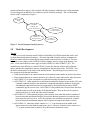
Figure 1. Overall integrated analysis process ................................................................................................ 2
Figure 2. Macro for translation from relative to global coordinates............................................................... 4
Figure 3. Process flow for integrated design/analysis at LaRC....................................................................... 5
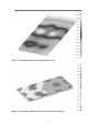
Figure 4. Thermal gradients on optical bench (in °C) .................................................................................... 9
Figure 5. Structural x-deflections due to thermal load (in meters).................................................................. 9
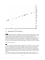
Figure 6. Translation to optical code: single optical beam path with deflection in mm.................................. 10
Figure 7. Sample relational file: PATHS.DAT............................................................................................... 16
Figure 8. Partial listing of sample run input file: tran.prt ............................................................................. 17
Figure 9. Partial listing of sample run input file: rot.prt ............................................................................... 17
Figure 10. Partial listing of Code V runstream file: samplerun.seq ............................................................... 18
Figure 11. Partial output of sample run, file opticalrunDEF1.SEQ ............................................................... 19
Figure 12. Sample Execution Run of PATCOD ............................................................................................ 20
-i-