1
Application Note AN018
Hints
1) Always perform calibration
CC1000 must be in LOCK both in Rx and Tx. Read back contents of register LOCK[0] after
calibration or monitor the CHP_OUT (LOCK) pin. Remember to set the LOCK_SELECT[3:0]
to '0001' in the latter case.
The calibration values are stored separately for each frequency register when single
calibration is used. Therefore, in a single-channel application, it is sufficient to calibrate once
in Rx and once in Tx when the system is powered up. Once this is done, the system can
change between Rx and Tx by writing to the MAIN and CURRENT registers, and no
recalibration needs to be performed unless one of the recalibration requirements stated in the
data sheet occur.
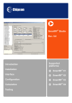
If you use the CC1000 Development Kit and SmartRF Studio press ‘Reset’, ‘Update’, and
finally ‘Calibrate’ in the SmartRF Studio Normal View to perform calibration.
2) Calibration: ALARM_L and ALARM_H
The correct VCO capacitor array ("digital" varactor) is found during calibration. The charge
pump current is adjusted to give the correct loop filter bandwidth.
If the VCO is not able to tune to the correct frequency, the tuning voltage will end up at 0 V or
at VCC (3 V). This will be indicated by ALARM_L (too close to ground) or ALARM_H (too
close to the VCC). Note that the PLL can, in some cases, lock to the desired frequency even
if the ALARM bit is set.
If the ALARM bit is set there could be several causes: The crystal or its programming is
wrong, the frequency programming is wrong, or the VCO inductor is wrong.
3) VCO tuning range
CC1000EB-434 should cover the frequency range from approximately 433 MHz ±10%.
CC1000EB-868 should cover the frequency range from approximately 868 MHz ±12.5%. If
you have made your own PCB layout the VCO tuning range might be changed. Check the
VCO tuning range as follows:
Set the frequency to a low value (TEST5=3F hex, TEST3=10 hex). Measure the output
frequency. Similarly, set the frequency to a high value (TEST5=30 hex, TEST3=17 hex).
Measure the output frequency.
Based on these measurements you can check whether the VCO tuning range is OK. Is your
desired channel within this VCO tuning range and is the channel centered satisfactorily? If
not, you will have to change the VCO inductor.
4) Check the current consumption
Approximately 25.4 mA in Tx (max power) and 7.7 mA in Rx. See CC1000 data sheet for
more details. You will also get values from Smart RF Studio.
SWRA073
Page 2 of 11