1
Chapter 3 Specifications and Fundamentals
Section 2 Fundamentals
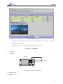
The block diagram below shows how the instrument works.
RF Signal
Amp
Attenu
ator
IF Process
Log. Amp.
Mixer
LO
Demod.
TS Analysis
Program
Play
Detector
Disp.
Keyboard&
TouchPanel
CPU
Module
Remote Control
Power Supply
Figure 3-1 Block Diagram of AV5462
The attenuator at the input of the instrument adjusts the level of the measurement signal to the
level range that the mixer can handle without overdriving it. With the input from LO(local
oscillator), the mixer converts the RF input to IF signal. After the amplification, IF process and
55