1
DPB2 Technical Reference - October 31, 1996 - Systronix®, Inc.
Asserting the relay output causes the buzzer to emit a tone. The sample programs
(DPB2E_X.BAS where X is the current revision) include a routine which creates a brief audible
click when a keypad key is pressed, as well as a longer beep when other keys are pressed.
ANALOG to DIGITAL CONVERTER
An 8-bit ADC is provided on DPB2, with a reference adjustment VR2, and input labeled at JP16.
You can adjust the reference continuously between 2.5 and 5.0 volts. This gives your
conversions a resolution of 9.8 mV to 19.6 mV per bit. Resistors R10 and R9 are an input
attenuation network. If you increase R10 you can increase the input range of the ADC.
VADC = VINPUT * R9/(R10 + R9)
For example, if R10 is 10 Kohms, the input range of the ADC will be 0-10 volts. DPB2 ships
with R10 of 10 ohms, in which case the input range is 0-5 volts.
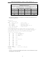
FILE ADC*.INC includes code to read the ADC. Program DPB2E_B.BAS demonstrates this
also.
ADC Throughput
The TLC549 ADC conversion time is typically 17 usec. Total access and conversion time is 25
usec. This allows up to 40,000 conversion and access cycles per second. As a practical matter,
this is limited by the speed of the 8051 at 12 or 16 MHZ and the rate at which your application
can process the ADC data.
The driver in ADC_E.INC takes about 50 usec (at 12 MHZ) to read the ADC value. If you store
the value in memory and/or manipulate it with BASIC instructions this will add more time. A
reasonable throughput estimate at 12 MHZ might be anywhere from hundreds to a few thousand
samples per second, depending on your application.
19